Very high winds had damaged the 70' "temporary" tower put up in 2011 and this was seen by my wife as a divine suggestion to get on with something more physically substantial. When the Almighty and my wife are on the same side of an issue, my job is to not ask questions and instead get moving! That's how the project got started. And from the kick off in March 2017, it took about 9 months from the decision to put up the towers until they were operational. Work will extend well into the 2nd year before things are 100% complete. Then again, in the ham-radio context, "complete" actually means "done for now." Building Permit First step was getting a BP. One of the attractions to this QTH was a ham-friendly zoning code with ham radio towers specifically allowed. The neighborhood has no HOA or other deed restrictions that preclude towers so I expected nothing would realistically kill the project. First step was getting a BP. One of the attractions to this QTH was a ham-friendly zoning code with ham radio towers specifically allowed. The neighborhood has no HOA or other deed restrictions that preclude towers so I expected nothing would realistically kill the project.
However the general trend in communities is not to encourage tower building. Additionally I was asking to permit 4 towers total and did not want to risk a second-guess on my tower count. To ensure a smooth building permit issuance, the services of Fred K1VR were used. Fred is a communications attorney who makes his services available to the ham community at very reasonable rates (as far as lawyers rates go, that is). He literally wrote the book on permit planning for hams. Thanks to Fred's careful preparation of my application, I was granted without exception a BP for all 4 towers. 3 were actually built (the 4th tower later determined to be unneeded). Only two county inspections were required - rebar cage inspection prior to concrete pouring and a final inspection. The rebar cage inspection proved to be the tough one, but not for obvious reasons... Delays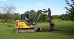 2017 was extremely wet with rains nearly every week and that prohibited getting heavy machinery into the yard out of fear they would become stuck in the mud. Nearby hills drain down onto my land helping to keep it green in the summer which normally is great but it also means it's one of the last areas in the neighborhood to dry out. 2017 was extremely wet with rains nearly every week and that prohibited getting heavy machinery into the yard out of fear they would become stuck in the mud. Nearby hills drain down onto my land helping to keep it green in the summer which normally is great but it also means it's one of the last areas in the neighborhood to dry out.
Eventually a dry couple of weeks in May were dry enough for the tower base and anchors to be dug using a small excavator. 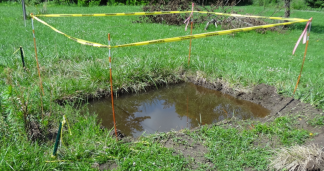
Unfortunately it would be another 3 months before dry enough conditions would exist before the holes would dry out enough to facilitate the county-mandated rebar cage inspection. For most of the summer the holes looked like this (left) - standing water in the 4x4x6' hole. Even when the water was pumped out(right, below), the colapsing walls were a battle to square up each time - hoping the recient rain would be the last for a while... 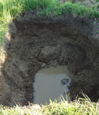
In discussion with the county they wanted to see a hole with no more than 1" of standing water in the bottom - something that seemed impossible to achieve given the rains that year and the high relative water table of the site. Rebar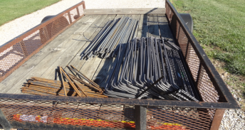
I had no prior experience with rebar however in retrospect the task was a lot simpler to comprehend once I got the basics. A local fabrication shop was able to make complete sense of the Rohn specifications and provided me with a trailer load of ready-to-assemble rebar. 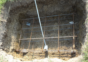
The primary concern of the inspector on the rebar cage was to have a few inches of clearance between the edge of the rebar and the earth. A cage prior to concrete pour shown here. The cage is 4'x6'x1' high. Initially the holes were dug by the excavator pretty close to this dimension. But note how much larger the hole (photo left) is than the cage. That's due to the erosion that occurred with the holes full of water. Soil would dislodge from the higher edges of the hole and collapse in requiring removal by hand. Fortunately two neighbor kids were willing to get literally knee-deep in mud for a price! 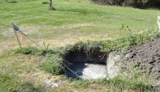
The sequence was the same most of the summer. We would get a few days of dry weather in the forecast, I would pump out the holes using a dirty-water pump and portable generator, wait a few days for the holes to dry out enough to get a neighbor kid into the hole to square up the corners. And then it would rain again... One hole remained exceptionally resistant to drying enough so I built a sump well in the center of the hole. A 5-gallon utility bucket was cut down to about 1' high and holes were drilled in the sides and bottom. A similar size amount of dirt was removed from the bottom of the wet hole and the bucket stuck in the hole. The top of the cut-down bucket was roughly even with the bottom of the hole. That allowed me to drop the water pump into the hole resting in the bucket where it would pull all the water out of the hole leaving just an inch or so on the bucket bottom. By the time the inspector had arrived the water level had reached the top of the bucket but not started to rewet the hole allowing for a "clean inspection". 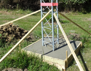
It would be September before a long enough dry period came along to allow for the final hole prep, rebar placement, county inspection and finally concrete pour. A total of 24 yards of 4000 lbs concrete pour later - the tower project was finally starting to look like an actual tower project. Shown here is the 40m tower base right after pouring. And above one of the guy anchors finally filled with blessed concrete. 2 days after pouring the concrete we had heavy rains that continued the following week. It was a great feeling to have rain come and not feel dread for the first time all year. Parts is PartsWhile the hole / rain / concrete saga was unfolding that summer, the hunt for tower parts was ongoing. Here are a few notes on some of the items that went into the towers. 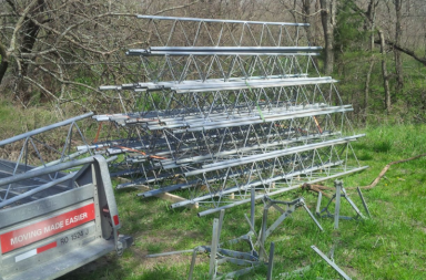
Wanting to put up bigger antennas meant larger towers than the 25G I had used in the past. Fortunately I ran onto some 55G along with guy brackets and beacon plates and that got the project moving. 55G would allow any possible combination of antennas I would ever put up. 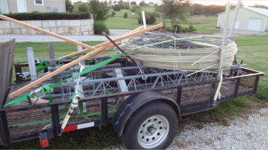 Another bit of luck was going down to help K5GO take down towers at his contest station. I brought back his old fiberglass rod, grips, a few additional sections of tower, control cable, many turnbuckles and the entire suite of FT5ZM dxpedition beams. Another bit of luck was going down to help K5GO take down towers at his contest station. I brought back his old fiberglass rod, grips, a few additional sections of tower, control cable, many turnbuckles and the entire suite of FT5ZM dxpedition beams.
The fiberglass rod had been up 10 years and was in good shape but had the usual layer of fiberglass bloom which flew off into the air when I handled. By the end of the very exhausting day I was so covered in fiberglass debris that I tossed my clothes into the trash after a very long shower trying to scrub away all the tiny bits from my skin. 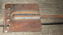
The Rohn spec for anchor rods for a short 55G tower is pretty light by my eye and I wanted something more substantial - just in case I happened to run into the anchor with a mower or something else bad happened. A local welding shop built my anchors out of 7/8" rod and 3/8 plate. They follow the Rohn design for one of their larger rods. The anchor rods were finished with galvanized paint following cleaning prep. 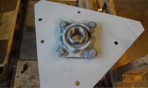
Thrust bearings were built from commercial bearings mounted on the beacon plates. I had used a similar Dodge bearing on another tower and after 5 years it was in excellent condition. The aluminum Rohn bearings in my bone pile are in a sorry condition and while the Dodge bearing is not officially endorse for this kind of application, in my opinion they are going to work at least as well as the Rohn offerings. 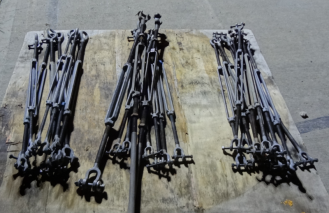
A lot of turnbuckles were needed. The 1/2" size were easy to find (~11,000 lbs breaking strength) and those I used for most of the tower guys. For the top rank of guys on the 55G towers I used 3/4" turnbuckles (~25,000 lbs). Overkill is Underrated. 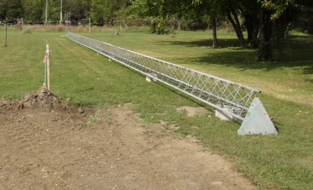
At left the 20m tower sections have been assembled and awaiting attachment of the guy brackets and rework of the beacon plate. Fiberglass Rod GuysI eventually used fiberglass rod for the tower guys. By far the most common material is EHS steel followed by Philstrand. I've been asked many times about this decision so the following recounts the background leading to this decision. 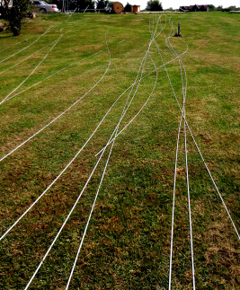 EHS steel guys work fine and have the advantage of being low cost especially if unbroken lengths are used. But as the need to place antennas on the tower below the rotor is considered, steel quickly looses it's attractiveness due to interaction with the antennas. Breaking up guys with insulators can reduce interaction but the length becomes more important as the frequency goes up. The more bands you plan to run on a tower the more difficult this issue gets. Based on a lot of modeling I finally concluded that I could not implement segmented guys due to unacceptable residual interactions the models forecasted - even with ideal placement of insulators. EHS steel guys work fine and have the advantage of being low cost especially if unbroken lengths are used. But as the need to place antennas on the tower below the rotor is considered, steel quickly looses it's attractiveness due to interaction with the antennas. Breaking up guys with insulators can reduce interaction but the length becomes more important as the frequency goes up. The more bands you plan to run on a tower the more difficult this issue gets. Based on a lot of modeling I finally concluded that I could not implement segmented guys due to unacceptable residual interactions the models forecasted - even with ideal placement of insulators.
Shown at left, long runs of new fiberglass rod unspooled and checked prior to cutting. Philistrand is a fine solution and has no interaction issues - however it's simply cost prohibitive, especially with the higher strength varieties. There are a couple of rope-like materials available now but the cost of those materials has become high as well and the expected life an unanswered question. The remaining alternative is fiberglass rod which has a mixed reputation. Some guys (K5GO for example) have used it without issue at all where others (W3LPL for example) have reported problems with it. As with many things in the ham universe, getting the facts stripped from the subjective opinions was not simple. The primary issue of concern seemed to be primarily to how well the rod "wears" with UV exposure over time. I spent quite a lot of time digging into the UV issue and after discussing the topic with several makers of commercial-use fiberglass rod used in construction materials I became convinced the life of the rod was going to be adequate. What apparently happens is that the fiberglass "blooms" with the outer layer being affected by the UV and puffing up and to the extent the effective diameter of the rod is decreased, the strength of the rod drops slightly as well. UV stabilizers are added to the fiberglass rod when it's made but they do not fully prevent the blooming effect. The key point is that the degradation does not continue beyond a surface effect as the outer layers once having bloomed then serve as a shield against UV penetrating further to the core of the rod. Over long periods of time the bloomed material does eventually abrade away with exposure to the elements with a rate is in the range of 10% loss of tensile strength over a 10 year period of time as a rule of thumb. The most commonly used size of fiberglass rod is 3/8 which has a tensile strength similar to 3/8 EHS - around 13,000 lbs breaking. By contrast the Rohn spec for my 120' towers (90 MPH 222/G) calls for 1/4" EHS (6700 lbs) on the top set of guys, and 3/16 (4100 lbs) on the lower guys. That means to me the fiberglass guys can degrade up to 50% of their original strength before they start hitting the minimum Rohn specification for guy strength. If the 10 year / 10% strength rate holds true, then I believe the fiberglass guys will be adequate for the 25 year life span I hope to get out of them - and that assumes no intervening replacement is performed. There are some creature comforts in working with the fiberglass rod - it's incredibly light weight compared to EHS. Easy to cut and easy to attach grips. There are some issues with fiberglass rod as well - the number of suppliers for rod on a spool are few, the spool must be large or the rod may splinter, and fiberglass needs to be handled with gloves. Finding grips built specifically for fiberglass is difficult as well. For my final tower installation, I used new rod on the 55G and reused the old rod from K5GO on the 160m tower. It's been a fine solution and I've been pleased with the results. 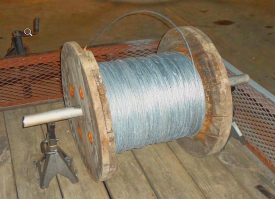 Some EHS was used - at the bottom end of the fiberglass rod. The top rank guys of the 20m and 40m towers was terminated with 3/8" EHS and all the other runs were terminated with 1/4" EHS. Shown left is the spool of 1/4" EHS mounted on some jack stands to allow the cable to be pulled off at a controlled rate. I learned the hard way that spooled EHS wants to unspool in the worst way possible... Some EHS was used - at the bottom end of the fiberglass rod. The top rank guys of the 20m and 40m towers was terminated with 3/8" EHS and all the other runs were terminated with 1/4" EHS. Shown left is the spool of 1/4" EHS mounted on some jack stands to allow the cable to be pulled off at a controlled rate. I learned the hard way that spooled EHS wants to unspool in the worst way possible...
Hardline Dreams and Good LuckI remember K9CT giving a presentation at Dayton one year where he was explaining the purchase of "hardline by the mile" for his big contest station. And indeed when I did the quick estimate of the amount of hardline I would need for my much-simpler site, it bumped up to near the one-mile length amazingly fast. Being able to do the entire project with hardline as K9CT did was just a dream at the time and so I focused on the most important need to start with - two runs of about 500 feet which would cover the length from the shack to the 20m tower, and between the two towers - allowing So2r operation which is my primary contesting mode. Initially picked up enough 7/8 for the tower runs - along with some 1/2" that I expected to use for runs up the side of the tower for the highest bands. Great! 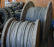 And later I was extremely fortunate to obtain an additional 1500' of very old but otherwise good condition 7/8 hardline last used in the 80's at nearby contest station. The cable had been stored in a covered barn and while thick with dust was away from rain. And later I was extremely fortunate to obtain an additional 1500' of very old but otherwise good condition 7/8 hardline last used in the 80's at nearby contest station. The cable had been stored in a covered barn and while thick with dust was away from rain.
With this hardine inventory in hand, a revision of what antennas would be cabled with what feedline was definitely warranted. It turned out that there was just enough hardline to cable all antennas with hardline, including the long run from the 40m tower out to the 160/80m site replacing some Davis Buryflex RG-213 I had left from the prior tower setup. The 213 would move to the 160m eliminating the planned use of half-wave lengths of 5/8 75 ohm CATV I had bought earlier in the year. The 75 ohm CATV would have worked fine but it would have required coiling about 100' of cable along the run somewhere plus there is a mismatch introduced as you move from the ideal half-wave multiple. 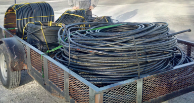 The final bit of luck was incredible as well. Among the goodies there was enough 48-wire control cable to finish the project, a couple of long runs of 3/8" 75-ohm CATV ideal for the receiving antenna runs and lastly some 7/8 solid aluminum hardline. The 7/8 line was unbelievable heavy and very stiff compared to the Andrews cable. The final bit of luck was incredible as well. Among the goodies there was enough 48-wire control cable to finish the project, a couple of long runs of 3/8" 75-ohm CATV ideal for the receiving antenna runs and lastly some 7/8 solid aluminum hardline. The 7/8 line was unbelievable heavy and very stiff compared to the Andrews cable.
After unloading the piles of wire sat in the yard for quite a while until one day I noticed the "50" marking in the part number of the 7/8 feedline - which offered hope to the desperate. It was a custom type from RFS and I could not find any internet reference to the exact part number beyond the family description. Later I tested the cable with a VNA and it proved to be 50 ohm stuff. Another change of plans on what antennas would be cabled with what feedline was required. In the end the 1/2" hardline originally planned for use with the 80m 4-square was retasked for the 160m vertical and the solid aluminum 7/8 stuff used for the long 80m 4-square run. 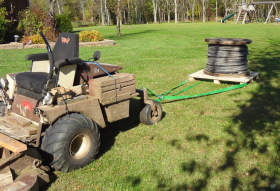
There were practical problems with all these materials as well - like how to haul them around on the property. The trailer worked well for most of it and a couple of unusual uses with the mower were found as well - like hauling around spools using a pallet as a skid (shown left). By the time the antennas were ready to be mounted to towers, all the antennas from 160-6 were cabled with hardline just like the big boys do it. Davis Buryflex is still used on all the antennas running from feed point through the rotor loop. And the 80m dipole is RG213 fed. But everything else has hardline. Rough hardline totals for the entire job came to: 7/8” 50 ohm 2900’ ½” 50 ohm 750’ 3/8” 75 ohm 2250’ In the photo below you can just make out the many long hardline runs that extend from the front of the picture to the back. With hardline, the measure twice-cut once rule is good advice indeed. Trying to decide how to optimally use the cable available was another significant task but I was happy to shoulder that burden! 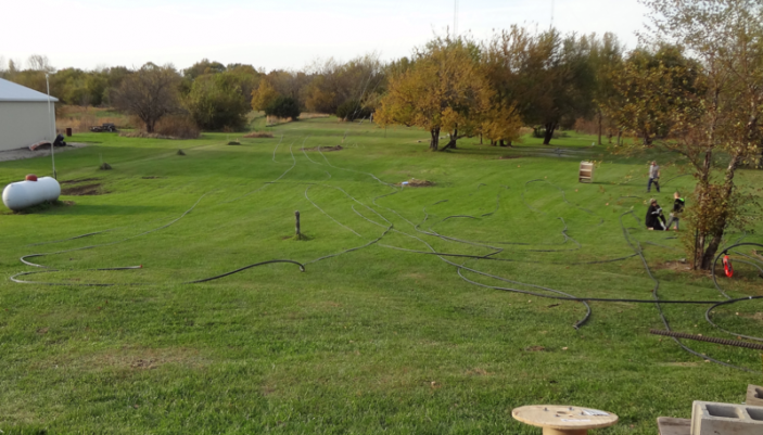
Connector Choices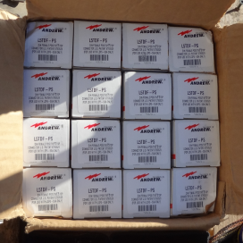 With no prior experience in hardline use, I had no experience with connectors but it became immediately clear that the world of hardline users are not fans of the ham-standard UHF series connector. 7/8 DIN and N seem to rule the hardline world and I had no experience with DIN and almost zero with N. I had heard that the big boys like DIN and so I bought DIN connectors for the tower-to-tower runs initially with the thinking that regardless of the fate of the universe, that is one connector that would never need to be replaced. I can say in retrospect, DIN is GREAT! Big and precise. Big and easy to work with. Easy to put onto hardline and looks great. I ended up putting 7/8 DIN on all the 7/8 cables on the intra-tower runs as well as on all the 7/8 runs up the side of the towers. With no prior experience in hardline use, I had no experience with connectors but it became immediately clear that the world of hardline users are not fans of the ham-standard UHF series connector. 7/8 DIN and N seem to rule the hardline world and I had no experience with DIN and almost zero with N. I had heard that the big boys like DIN and so I bought DIN connectors for the tower-to-tower runs initially with the thinking that regardless of the fate of the universe, that is one connector that would never need to be replaced. I can say in retrospect, DIN is GREAT! Big and precise. Big and easy to work with. Easy to put onto hardline and looks great. I ended up putting 7/8 DIN on all the 7/8 cables on the intra-tower runs as well as on all the 7/8 runs up the side of the towers.
There are some N connectors in use here - all of the 1/2" hardline runs have N connector terminations. And I used N on the 6m run at both ends of that link. On the entire project I have only had two connector related issues - one was on a N-connector and the other was due to nicking the center conductor of the LMR400 on a pigtail. No failures of UHF or DIN. When I mounted the first few connectors on hardline I had quite a lot of problems getting acquainted with the process. It did not help that the connector I had was not the right one for the hardline which took me quite a while to figure out as I assumed initially that it was my application method at fault. But once I deciphered the magic code between what connectors work for what cables, it was smooth sailing from there on out. |