Getting Gain and Directivity on the Cheap 80m Four Square A key consideration for the new antenna & tower setup was to implement an 80m 4-square. Unfortunatley it's not possible with the available land to have it in a stand-alone location so it was built around the 160m vertical out of physical necessity. Antenna ConfigurationInitially I had looked at the inverted-V type of 4-square which was favorably mentioned in the ON4UN. That design features vertical oriented dipoles suspended from ropes off a center tower with the element tips tilting into the tower at the top and bottom of the tower and was said to use the existing hybrid combiners with success. However after quite a lot of modeling work by AutoEZ creator Dan AC6LA, from the results of that work I was not convinced the actual performance of the array built in this configuration would work as well as reported. With a traditional vertical + radial field being the remaining alternative. The 4-square is built on a slightly oversized 71.5' vertical-to-vertical spacing which in modeling was slightly better than the cookbook 65-67 feet. Plus I reasoned that being a bit further from the 160m vertical would slightly reduce the interaction with that element. The 160m needs to be well grounded from a 80m standpoint to minimize it's impact on the 80m array - something that the DXE switch provides when the 160m antenna is not being used. I will add an 80m resonant shunt to the base of the 160m antenna which would provide some attenuation of 80m signals to the 160m feed as well. Vertical Element ChoicesIdeally a tower for each vertical would be put up providing a mechannically indestructable solution. While I had the tower sections to do the job, I could not find an economical and physically strong way to insulate the bases. Additionally the towers would need to be guyed which would require an anchor although the screw-type would work fine given the wind loading presented by the tower would be minimal. Another option was a free standing vertical made from aluminum tubing - here the cost was a problem. Given these factors and with winter coming closer each day, the quick solution was to drop wires from a set of 4 vertical ropes attached off the top of the tower and running out to the perimiter of the field where the 160m vertical was located. The ropes have pullys at the top and with the 4-square vertical wire tied to a fixed point on the rope, the position of the top of the vertical could be adjusted so that it was upright. It also allowed for easy trimming of the vertical element to resonance as needed once the final radial configuration was put in. 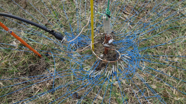 Radial Fields Radial Fields
The 160m vertical radials are below ground which left a free working surface on the ground. The plan from the start was to lay the radials on the top of the ground and let the grass absorb them over time. Overall each of the 4 verticals is in a clear part of the field but for some of the radials there are no-go zones (trees, creek paths, gravel drive, etc) where a full 1/4 WL radial would not be possible. So I put down at least 30 1/4 WL radials on each antenna as a minimum. And in the case that there was some limitation I increased the number of radials in that area greatly. Actual radial counts per vertical are as follows: NE 28 radials SE 36 radials SW 57 radials NW 65 radials A circle of #6 copper was laid out and the radials soldered on. Radials were made from #22 teflon coated stranded wire, pinned at each end and in low spots on the ground using landscape u-shaped nails a couple of inches long. In total there are about 200 radials among the 4 verticals. 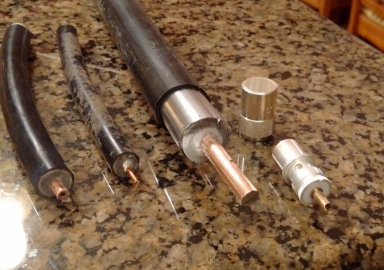 Feedline Feedline
The individual verticals are fed with RG11 foam centered coax. The high 0.81 VF resulted in long runs and easily accomidated the land topology as well as reaching across the concrete base from the DXE hybrid controller. Feedline from the 40m tower switch about 325' distant to the 80m antenna site is made using the 7/8 solid wall aluminum hardline (shown at right) with RG213 pigtails on each end - no attempt was made to minimize the impeadance bump for the transition as I thought on 80m that would be of no concern. 80m DipoleThe 80m dipole is suspended from the 20m tower at about 55'. A 4' length of angle stock is mounted to the tower giving a couple of feet stand-off from the tower for the center. The height is limited by the antennas on the tower and interactions with the 20m stack which was considered to be the higher priority. It's fed with Davis Buryflex RG213 cable that runs down the tower and hooks into the DXE 2x8 coax switch at the base of the tower. The ends of the dipole are suspended by rope runing to trees located about 200-300 feet out so the dipole has somewhat of a "V" shape. The ends of the dipole are around 40' off the ground at the low point. In use, the dipole is the better antenna on 80m within perhaps 500 miles. With distances beyond this, the 4-square is the better antenna in almost every case. The 4-square is often the better antenna in storm season because the directivity allows a reduction in QRN where the back side of the 4-square is against the storms and the guy being worked is on the front side. On receiving the HiZ 8-circle works fine on 80m although most of the time the full size 80m 4-square provides better results - somethign I have noticed on the 40m 4-square over the years as well. |