Signal Routing and Giving Lightning an Easy Path to Ground. Without Frying Anything. At least that's the plan! 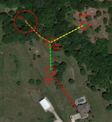
The system is composed of 3 towers arranged in a daisy chain setup. A junction box at the shack (house) terminates coax and control lines to ground. From there control and coax run out to the 20m tower, onward to the 40m and finally out to the 160m vertical. Each tower has a grounding system explained in more detail below. And at each tower are various antenna switches for band selection and for managing the stack combinations. There are 3 hardline runs between each tower and then another 3 sets to the shack. Each tower has a dedicated set of control lines - 48 wires for the 20m tower and 50 wires for the 40m tower. 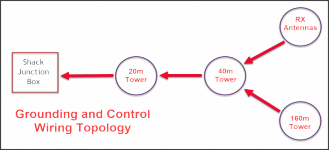
Control Cable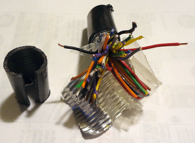
I had decided early on to keep the switching in the shack and run control lines out to the field. Lightning damage is a problem with a lot of the wireless and field located control solutions so keeping things hard wired seemed a the best choice from a reliabilty standpoint. About 100 control lines were needed to manage all the switching; about 50 to each the 20m and 40m tower. I was fortunate to find an ideal cable for the task (shown right). It's a direct-burial rated line with a heavy aluminum shield and 50 conductors of about 20 gauge solid copper wire dating from the 1980s. Unfortunately there was not enough to do the entire job with the 50 conductor stuff but another stroke of good luck had me litterally stumbling across another source of 24 conductor flooded wire made by AT&T that had been setting in a local's field for so many years the reel had deteriorated into powder by the elements. Flooded cable is a lot more messy to deal with when prepairing but I'm sure it will last my lifetime as the 50 conductor stuff will. The 40m tower was fed with the 50 conductor cable, and the 20m tower fed with two runs of the 24 conductor cable - enough for the task in both cases. In additon the rotors needed some large gauge wire for the motors plus the pulse sensor lines. I used 12/3 UG (4 conductor including the bare ground wire) for the rotor motor runs and to provide a path for the +28V DC line that eventually terminates out by the receiving antennas. For the pulse sensor I used two of the control lines but was sure to test that well before covering the trenches. It's proven a solid rotor control solution. Runs from the ground up the tower to the rotors were made with Wireman rotor cable which is a pair of 12 gauge plus a pair of 18 gauge. The Wireman cable is used in the shack as well for the runs from the Green Herron controllers to the shack junction box. Approximate control cable totals are: 50-conductor 500’ 24-conductor 1200’ 4-conductor 120’ 12/18 rotor 300’ 12/3 UG 770’ Tower GroundingShown below are the ground rod locations for the 20m tower. There are 8 legs of #3 insulated stranded copper extending from the tower. 8' rods are located at 6', 20' and 36' out from the tower. The 40m tower has a similar ground rod configuration made of 6 legs ground rods with the #3 wire connection. 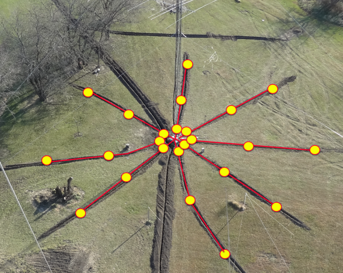
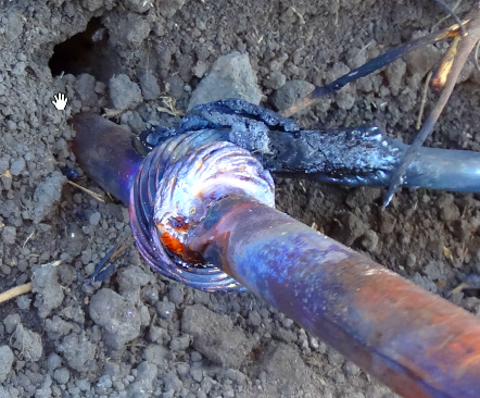
A high-temperature 15% silver brazed connection is used to bond the rod and ground wire - this is not a soldering method in the traditional sense as you need an acetylene torch to get the rod/wire hot enough to reflow the brazing rod. Cadweld and similar bonding types are superior for this application in that they would last longer and provide a fully melted blob interconnection. But with a fixed budget, I thought that a trade off of a cheaper bonding system in exchange for more ground rods would be better. 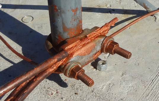
A Hager bronze clamp is used on each leg with the closest 2-3 ground wire feeds connecting to the clamp. An additional #6 solid copper bare wire runs between the 3 legs. Liberal use was made of copper-containing conductive grease in the hope that may assist in corrosion prevention over time - it makes quite a mess! 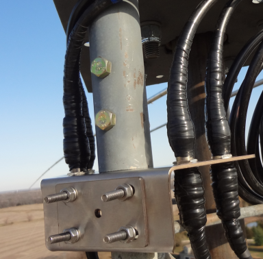
Antennas on the rotor are grounded at the top of the tower through a KF7P feed-through mount. And the coax runs for the same above-rotor antennas terminate into the Polyphaser mounted on another KF7P mount shown here. Antennas lower down the tower are just run down the tower without special treatment. DXE 2x8 switches are used on the two tower locations - the blue bungee cord holds a rain shield (not shown) in place to keep the elements off the DXE switch and associated feedline/control connections. 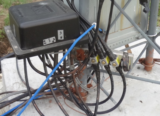
Control wires from the shack terminate into the junction box. Each wire is equipped with a shunt connected MOV for lightning as well as a LED/resistor/cap combo which provides fast indication of which lines are active. The terminal block on the left is complete; on the right wires are not connected yet. Wire pairs are twisted and further marked with letter beads to help with identification. The backing plate for this box is a 1/4" thick aluminum plate. Strap runs from the bottom of the sheet through the bottom of the box and ties into the tower ground ring wire. 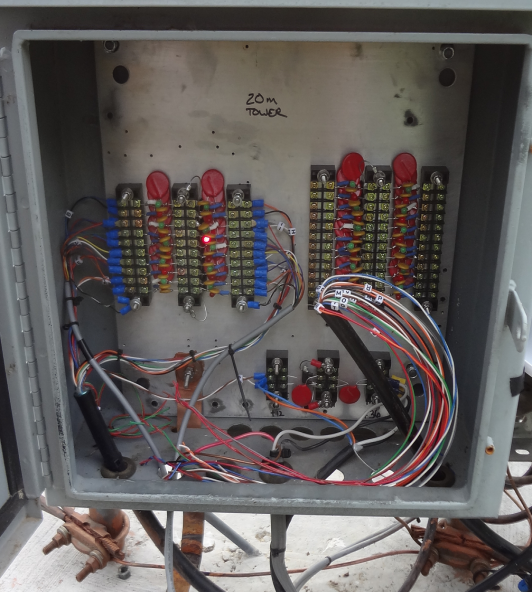
The 40m tower has a similar grounding structure. There are 5 antennas in on this tower which are run through Polyphasers. Hagar clamps, lots of messy copper loaded goop and the circular #6 connecting all 3 legs follows the 20m tower setup. 
The 40m tower junction box has more lines than the 20m as it hosts the control lines for the receive antenna site as well as the 160m/80m site. 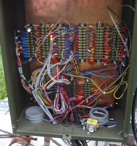
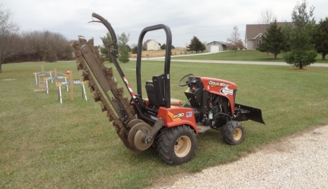
There is about 2000 feet of trench here on site and that was all finished in about 4 hours with this Ditch Witch self-propelled Cuts about 6-8" wide and up to 12" deep although the machine will dig deeper. machine. Highly recommended for high volume trenching. Digging by hand is of course possible but the machine is a huge labor saver especially when you have to navigate roots and rocks. Shack Entry GroundingHardline runs from the towers enter into the shack through a wall-mounted junction box. A local ground network of 20 rods are constructed in a similar fashion to the towers. 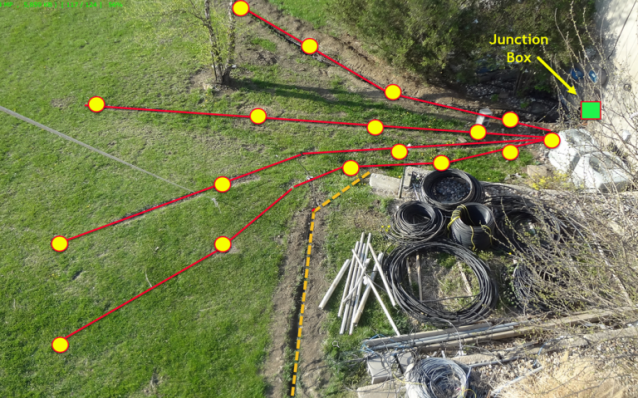
The shack entry box is built by KF7P Chris and is an excellent platform. For the latest tower setup I mounted terminal strips on the backing plate to accommodate MOV clamps for the 100 control lines that exit through the panel. Most control lines also have LED/resistor/capacitors on them which are a huge time saver when troubleshooting. The site topology is focused on So2r so only two hardline runs are needed from the towers back to the shack - the 3rd connection is for a dedicated 6m feedline. The copper backplate connects via two runs of strap down to the ground network. 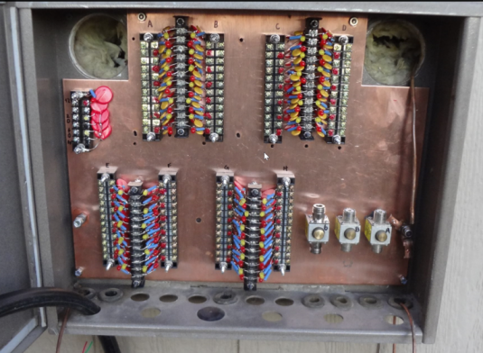
Here's a close-up photo showing the components mounted to the terminal strips. 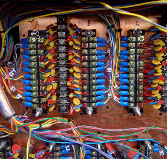
|