Modern Magic --> Details on the site, neighboorhood and beverage are found HERE <-- The Hi-Z 4-8 pro circle array was a concern given it's an active array and it's 300' distance to the 160/80m. But the Hi-Z guys told me not to worry - and they have been right; the array has been solid since it's installation. When we bought this QTH, my complete lack of experience with outdoor antennas left me completely unprepared to be an adequate judge of a QTH's suitability for receiving antennas. However, we seemed to have got lucky this time and things have worked out pretty well. More details on the RX antennas follow. Directional Receiving ArraysOne of the first lessons a budding low band want-to-be contester learns is that receiving success is all about controlling the noise. This is a difficult concept to grasp because on the higher bands, we generally talk about the other guy's signal - and how a beam, etc, may help that. But the point that W8JI was trying to make when I seriously first considered this at the 2010 W0DXCC convention was that putting the null on the noise was the right approach. So when looking for a low band solution, I wanted to pick a ready-built solution that offered a good ability to precision null the noise. And that would fit in the space available. Initially, I considered building a pair of bi-directional beverages using the available DX-engineering materials. However, without having anything in the junk box, all the components would have to be purchased and the combined cost was significant. And while a beverage for the NE/SW direction would not be difficult to put up, the SE/NW direction would have to run along a set of trees on the property which (at that time) could be reasonably called dense forest. With the ice we have here, falling tree branches, etc, would be a constant challenge for that SE/NW beverage. The competing solution was to consider one of the dedicated receiving array systems - something I had heard of but had no prior experience with. Initially I considered a 4-square type for 160-80 as the goal but as I got further into it, the final decision was to go with a broadband version of an 8-element circle array. The considerations that lead to this choice were several and explained below. The objective comments about each item are here - as well as some of my thinking about each at the time as I remember it now... First, the buffered array sizes were reasonable. While I have plenty of land, a lot of the area was covered with tree, brush or otherwise cluttered. My goal was to place the array as far as I could away from any other source of QRM, and to try to stay away from the eventual location of the 80/160m vertical (planned but not built at that point). And with winter coming fast (it was November already) and temperatures dropping, there was not time for a land clearing operation. Full sized receiving systems can be simply huge (both in height and in ground footprint) - in some cases, so size was a key selection criteria. [Mental thought at the time - the area where the RX array needed to go was filled with poison ivy and overgrown live and dead trees. Finding the right place to put a few verticals was going to be tough the larger that circle became. A vote for the buffered arrays here.] These smaller arrays use a voltage-fed buffered vertical approach which means the ground system can be a simple 4' ground rod. The reason unbuffered passive arrays require a large ground is because the feed point impedance is so low - which makes ground losses a major focus that is what drives the big radial fields. The buffered type has a very high feed point (around 50K ohms) making a small rod a low-impedance ground connection, by comparison. Great - no ground radials to lay down - especially since that would have required a lot of ground prep as well! [Mental thought at the time - crawling around on freezing and wet ground clearing radial fields vs. hammering in a few ground rods - buffered array of some kind is the clear winner!] Next, the verticals themselves are non-resonant and relatively short. Typical sizes for vertical elements are in the 7-25' high range. The larger the element, the more signal there is. However, as the element is larger, the element starts to move toward resonance and the feed point changes with frequency to a greater extent as resonance is approached. Buffered arrays with ideally balanced verticals and feeds can have amazing back-side rejection. That balance is harder to maintain the closer to resonance you go. This 7-25' range gives the builder a lot of flexibility on the materials used. [Mental thought at the time - I could use some 10' lengths of electrical steel galvanized conduit, a bit of PVC and some short electric-fence-post material all of which were available at the local stores. And if the 10' proves too short, then next spring I can expand them to nearly 20' just by adding an extension of conduit. I can save some bucks here with this simple fabrication plan - but it limits my height. That's great because as I look at the trees, cutting away branches 20' up is another challenge I'm not ready to handle just yet. That does it - buffered solutions of some kind are the winner.] And finally, the topology of the array is another variable. Here there are a couple of companies and a lot of systems to pick from. The 2, 3 and 4 element systems are most common, with 8-element systems generally being the most sophisticated - more elements generally means more directional flexibility. Active systems tend to be either single-banded with excellent performance - or broad-banded (meaning 2+ bands coverage) but trading some performance away in exchange usability over a couple of bands. [Mental thought at the time - I determined that the 4-element system would do the trick. But considered that this is the kind of thing that you buy one time - and use for many moons. Also, the big boys have the 8-element types. So I eventually ordered the 8-element with the final added rationale that had I bought the 4 element type, I would always wonder just how much better the 8-element was...] In my case, I had just put up the 40m 4-square and did not know if the 8-circle would be a better performer or not; so my need was something that covered 160 and 80 with good performance, but would have some functionality on 40m providing me with an alternative RX antenna on that band as a backup. Juggling all of these options, the somewhat logical and certainly final selection was to go with the Hi-Z 4-8 PRO 8-element buffered vertical system. The Hi-Z 4-8 PRO 8-Element Buffered Vertical ArrayIt's basically a pair of 4-square receive systems interlaced into an eight-element array. It covers 160m-40m but is really optimized for 160/80m if the larger diameter circle layout of 113' is used. The system has quite a few boxes in total. In addition to a small direction-setting box that sits in the shack, out in the array installation center we have a set of 3 boxes and the phasing/interconnect lines. One of the boxes is a preamp that drives the coax running back to the shack. The other two boxes handle the phasing line and other switching aspects. This block diagram from the Hi-Z manual shows how it all goes together. 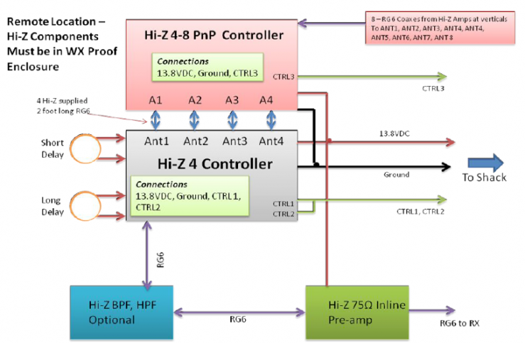
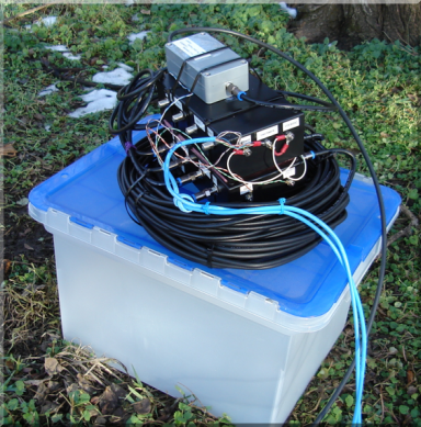
The short-delay/long-delay cables are not part of the standard system offering, however, the Hi-Z guys will build those up for you at a reasonable added charge. With these delay cables added, the entire system is ready to hook up on arrival. Delivery took only a few days even with the delay cables added to the order. I pre-assembled the outdoor items into a nice stack and hauled it out to the field. VerticalsOnce the order was made, the task of identifying the exact location of the 8 verticals was tackled. If you have an open field, then this is very simple. But if you have trees and brush in the area, it's quite a bit harder. The final result is shown in the picture below. 4 of the verticals can be seen (indicated by arrows) . The control items are in a large green-colored plastic tub (inside the green circle). 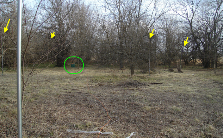
Why is this a challenge? The goal is to get the circle as exactly measured as is possible - meaning down to the inch or better, if you can. The position of the verticals has a direct influence on the ultimate directivity and symmetry of the array. 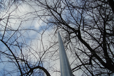
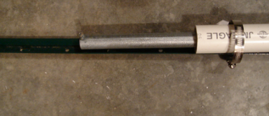
The instructions in the Hi-Z manual are setup on a X-Y rectangular layout. I initially tried to use that but with all the stuff in the way, it was a complete failure. Eventually I found it much easier to calculate the element-to-element distance and with a pair of long tape measures, laid out a single circle. That method is nice because you have somewhat of a cumulative error check when testing the distance from the 8th element back to the 1st element. One of those "why didn't I think of this earlier" moments!!! The layout was quite a bit more time-consuming that I imagined even after switching to the radius + offset method and the final position required quite a bit of trail and error. It took several attempts initially before getting one "good" set of positions as I always ended up with one vertical needing to be placed into the same spot that a tree was located, or where the limbs would interfere, or were dead tree limbs would need to be moved out, etc. After getting a good initial position, I went around to each of the positions and looked at what was near the vertical. After some consideration and weighing the compromises, I moved each of the circle's elements to a final resting point - and then did one more final measuring to fine-tune each element's resting position. The picture (above, right) gives you an idea of what some of these vertical environments look like... For the physical construction of the verticals, the assembly looks like this. 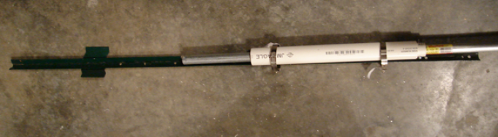
The element is built from a length of 10'x3/4" galvanized electrical conduit. 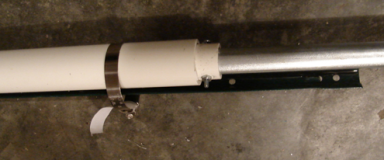
A pair of concentric PVC tubes of about 12" were cut for each vertical. The smaller PVC tube was secured to the pipe with a long screw. A small screw is mounted at the end of the conduit and will later serve as a connection point to the buffer amp. The verticals were assembled in this order: - The small fence post is driven into the ground.
- The ground rod is driven into the ground.
- The larger PVC size is held to the post by a pair of hose clamps.
- The conduit with it's slimmer PVC already attached is slid down inside of the larger PVC tube.
- The element rests the top larger screw on top of the larger PVC tube. The screw is rotated away from the post and the element is taped in place to prevent rotation and keep water out of the tubing.
In each case, care was taken to maximize "sameness" - meaning the ground rods were driven to the same depth, spaced away from the fence post by the same amount, and the verticals spacing above the ground was the same for each vertical. At that point, the buffered-amp was mounted to the base of each post. And the wires were attached to the vertical, each attaching wire (both element and ground side) were trimmed to the same overall length in line with our sameness objective. Looking at the final result, in these two pictures you can see the mounting detail. Plastic zip ties secure the box, and the coax is wound around the post to provide a stress relief in the event the cable is snagged for whatever reason. 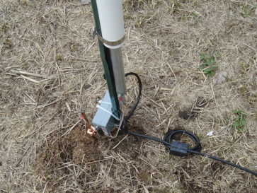
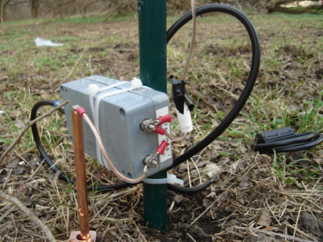
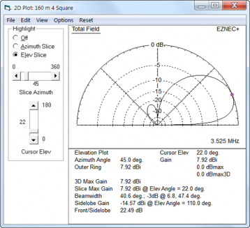
Broadcast Band IMDThe system worked fine right from the start. However, on my bandscope, I could see some spurs showing up indicating some IMD products creeping up from the AM broadcast band. In discussing the problem with Hi-Z, they suggested I try some Hi-Z supplied passive notch filters. You can see the small filter attached to the terminals in the photo above, right (white small tube). I added some sophisticated weatherproofing (a bit of black electrical tape) over the top end to keep the water out. And that was the end of the IMD from the circle. Closing Comments - Hi-Z 4-8 PRO circle arrayMy first experience with an active system has been a good one. Rotating the array can be an amazing experience as you click from one to the next and see a given signal pop out of the noise. I eventually got the 80/160m vertical put up right before the 160m contest (about a month later) and that was a fun contest as a result. No end of signals to work. And from a noise standpoint, there is no comparison with my transmit vertical - 100% of the time the circle is better. The circle does have one behavior which may or may not be of benefit. That is the same thing that makes it so quiet (directivity) is also a problem when you don't necessarily want as much directivity (contesting). If you are lucky enough to have a strong transmit signal such that you can leave the array beaming in a single direction, that works great. But I sometimes need to work that direction knob in the shack quite a lot. And for a fast exchange contest like CW, that can drive you nuts as well. The lesson here is that there is no free lunch. If you get your quiet performance through directivity, be aware you will need to get that directivity working in the sender's direction! Which leads me to the one and only criticism of the system. As delivered, the direction switch has a hard-stop at 0-degrees (north). My preference is to have no hard stop, and if a hard stop is required, then let it be at about 250 degrees or so. My solution for this was to turn the control box over, so that it sits upside down, that move the stop to the 270 degree point. And then I rotated the wires in the array, moving each vertical ahead 4 slots (so vertical 1 became #5, vertical #2 became #6, etc) which restored the switch pointed up = array beaming north functionality. It's almost not noticeable other than the Hi-Z label is inverted. I also moved the rubber stand-off to the top (now bottom) of the case and it's worked great since. Not the most elegant solution but it worked for me! Modeling the CircleA proxy model of the 8-circle is to build a basic 4-square model. Plots for the 8-circle from this type of model are as follows. This is based on the compromise phase line lengths (a split between max-RDF and max-F/R). 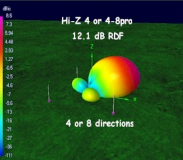
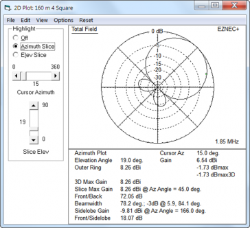
8-circle plots for 160m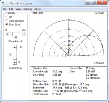
8-circle plots for 80m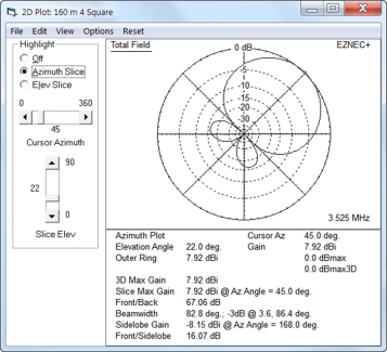
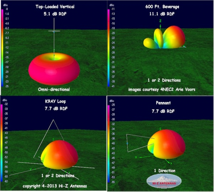
For the most part, the pattern remains mostly clean between the bands and is really amazing, when compared to the beverage who's performance is very tied to the frequency vs. length. This assumes an ideal current balance from the control box which is not realistic, however. But the result of current variance (either from the box, from the vertical positioning or other areas where the "sameness" goal is not held ideally) would be increases in the lobes somewhat. These variances - as well as the growing contribution of the fixed-length delay lines compared to the phase inversion transformer eventually cause the pattern to break down as frequency continues to climb. In general, I find the full-sized 40m 4-square to outperform the 8-circle . Hi-Z RDF Comparisons 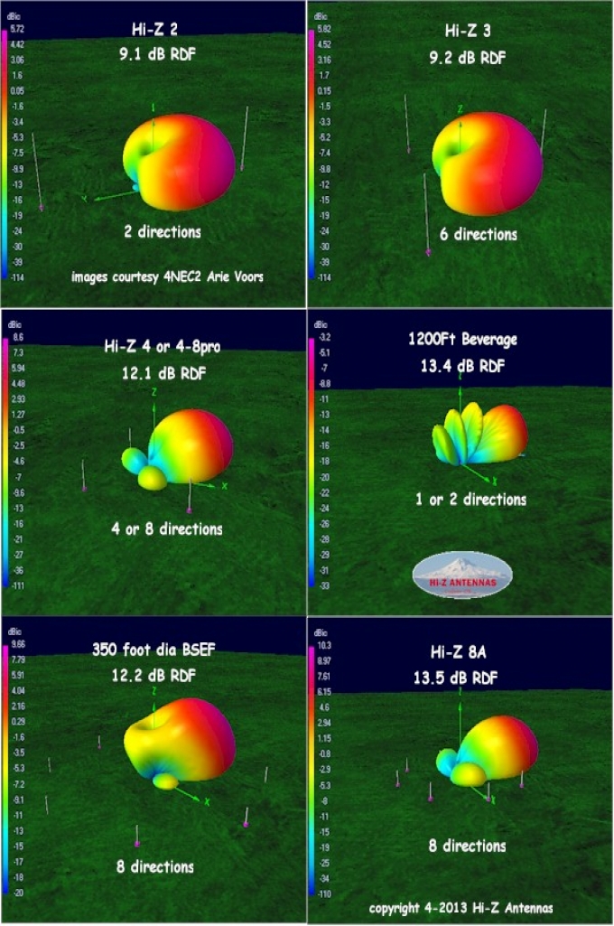
Circle and the Beverage - How They CompareI really need another season to get a better opinion of how the beverage works compared to the circle. At this point, I think I could generalize this way: For signals along the NE direction, the performance of the two antennas is similar. In maybe 20% of the cases, the signal will be a bit "better" on the circle, and in other cases "better" on the beverage. I say "better" because these are not objective SNR weighted determinations. For the most part, along the NE direction, either one of these antennas works fine. BUT... But once the signal comes from a bearing off the NE direction, the circle ALWAYS dominates. And I guess that's the ultimate beauty of the circle - you can point it at the source. Unless you have multiple beverages, then it's tough to get the same flexibility - not to mention you need a LOT more ground to put up a variety of beverages. Looking at the pros, there is only one conclusion. For example, ON4UN has beverages - not sure if he has a buffered array. K3LR and N0NI (to name a couple) have a Hi-Z system - and maybe a few beverages. K3LR has a low dipoles and who knows what else. So what was that conclusion? It's this: the more RX antenna options you have, the better chance you will have of picking up the marginal signal because for whatever reason, one antenna may work better for that signal than another one. And if you are chasing the weak ones, this may be the edge needed to pull the guy out of the noise. I'm glad to have both of these antennas at the ready. Making the comparisons is fun - and there is always a benefit to having a more than one antenna just in case something bad happens in a contest down the road. Finally having the beverage allows me to quantify comments about the circle array in a more useful way - "... compared to the beverage, the signal is ..." |