 The Monster of the Site has a High-End Heritage The Monster of the Site has a High-End Heritage
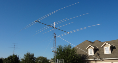
The completed beam mounted on the temporary test-tower for checkout is shown at right I started out with some Telrex beams in my bone pile and an idea that I could homebrew a 3-element 40m beam from the parts building it on the cheap. I had heard the Telrex beams were the top of the line back in the 60's and 70's but that despite a reputation for being built incredibly well there were comments on the internet that the Telrex beams (especially the 40m) would not stand up to high winds and tended to lose element tips. Sure enough with subsequent analysis running the DXE Yagi Mechanical application against the element construction, failures were predicted at speeds below 60 mph. With local wind speeds expected in the 85 mph range (in fact a wind speed that was encountered in March of 2017 and who's damage precipitated the entire tower project!), that limitation was definitely a problem. Of further concern was that all this analysis assumed aluminum used in the Telrex was equivalent to 6061 however I was not able to confirm that meaning it could be of some softer variant meaning actual failure speeds could be lower yet. A second use of the elements for a 30m beam was considered. I had always wanted a serious 30m beam as the band is a good DX band through the entire solar cycle and with most hams using wires on the band, a full size beam at height would provide a big signal advantage when chasing the rarer ones. Unfortunately the same mechanical analysis suggested element failures even in the shortened 30m length. I had been considering wind but ice loading is a problem around here as well. After some time playing with ice loading values in Yagi Mechanical, I determined that 100 mph would be a more suitable build-standard that any of these antennas I put up should meet. Especially with big antennas up on the rotor for which falling elements could damage lower antennas on the tower and generating more troubles. The 4th tower - originally earmarked for the WARC bands - would not be built due to the difficulty of clearing the trees in the area along with a very wet summer. Fortunately modeling indicated that the 30m beam would coexist fine with the 10m/40m antennas planned for the 40m tower without interference leaving 12m and 17m without a home for the moment. It looked from the same modeling analysis that 17m would play nice with the 10/30/40 beams on the same 40m tower - but 12m would not. That solved the immediate WARC antenna problems - and with the solar cycle heading down, I ignored 12m thinking it would literally be years before a beam on 12m would be needed. 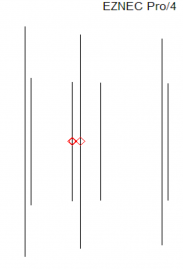
With 3 beams planned for the 12' of available mast above the rotor, the logical place to put the 17m beam was to try to interlace it on the 30m beam boom. The 40m elements resized for 17m duty would have plenty of strength for 17m service even if they were not built from 6061. And it looked like two of the existing mounting points on the old Telrex 40m antenna boom were close enough to optimal for the 17 director placement that it could make element mounting simple. Eventually a 3-element 30m beam with a 4-element 17m beam on the same boom was the final design choice. ModelThe model is relatively simple (shown right). Separate feeds allow simultaneous use of both antennas at the same time avoiding any shared-feed complications. The main challenge was to optimize gain and pattern while keeping enough spacing between elements to avoid unnecessary physical interaction. Fortunately while the 30m elements do move around quite a bit in the wind, the part of the 30m elements adjacent the 17m elements maintain their spacing very well. That combined with the minimal interaction between the two beams mean both antennas are pretty stable from an SWR standpoint even with winds. Model-Predicted Performance - 30m 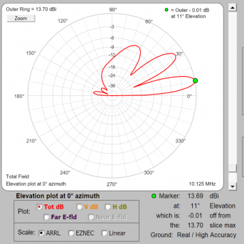
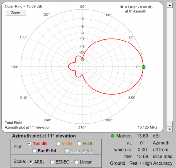
Model-Predicted Performance - 17m 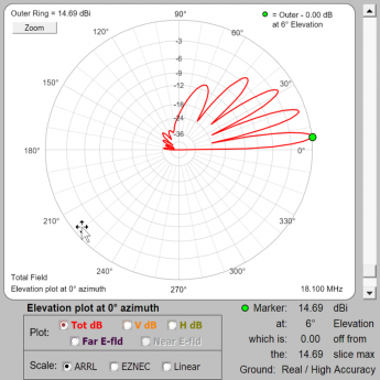 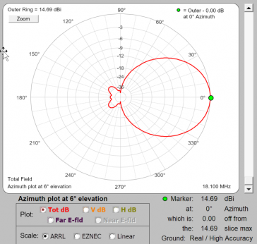
Building the Beam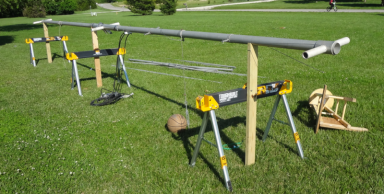 The boom (shown at right) is massive - 31' long, 3-1/2" OD and 1/4" wall. It had a wind survival rating of something like 150 mph so I retained it for the 30m beam project. The boom (shown at right) is massive - 31' long, 3-1/2" OD and 1/4" wall. It had a wind survival rating of something like 150 mph so I retained it for the 30m beam project.
For the 30m elements, new modern-blend 6061 aluminum was bought from DXE and cut in lengths that the yagi analysis tool indicated would give a 105 mph survival. I built full-size elements as that was a simpler mechanical and subsequent tuning challenge than using loaded elements. 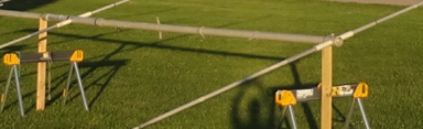
The 17m beam started with the D1 and D2 17m elements mounted in the original through-beam mount locations of the Telrex boom. 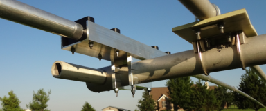
The REF and DE elements for the 17m beam were mounted to the boom using DXE saddle clamps and a G10 3/8 fiberglass epoxy board as the insulating mount. 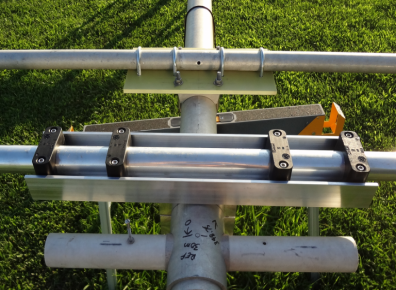
For the 30m elements, I bought parts from JK Antennas and duplicated their mounting method JK uses for their 40m beams which has a big aluminum U-channel and associated hardware. 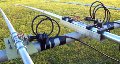
Both beams were hairpin matched. Type 31 cores with multiple turns of feedline through provided common mode choking. Number of turns and coil alignment was done with a VNA on the bench. The So239-to-pigtail adapters are courtesy of W8WWV. 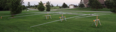
The completed antenna show here on the saw horse platform used for assembly. 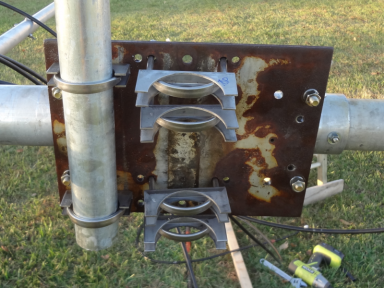
The original Telrex steel mast plate (12x12x1/4) was used with modifications to accommodate a 2-3/8 steel truss pipe. The original steel truss stranded wire was reused with new clamps added. The plate is literally too heavy to do anything other than just use! While the Telrex boom is massive, it's weight as well as the added elements results in the usual boom sag and so serious hardware was called for on the truss. Fingers crossed! 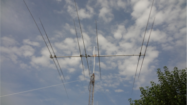
Another view of the finished antenna shown here under test. Only minimal adjustments were needed compared to the model to bring the antenna into tune. Measured F/BI tested the antenna's front-to-back with the beam on a 30' tower. A beam about 175' distant was used as the reference. The test is conducted by pointing the test beam at the reference antenna, running a VNA through-cal to establish a zero baseline, and then rotating the antenna away from the reference. The path will show loss (or gain if the cal was taken with the beam pointing away) - and that difference value serves as an indication of front-to-back. The actual values are less important than the general position of the curve which we hope is showing it's peak somewhere near the ham band. In both cases the F/B was very nicely represented, especially in the 17m case. The distance between the two lines in the plot represents the F/B of the beams. Ignore the +/- sign of the value - the beam was so huge and my rotor was having a hard time turning it so I did not want to rotate it another half turn to get the two references back to both positive or both negative. 30m plot is shown at left, 17m plot shown at right. 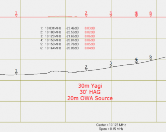 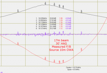 One Last Overlooked DetailOnce the antenna was mounted on the 40m tower, I had a rig on each antenna, eager to check it out. Everything looked great but at some point in the testing my Yaesu FT2000 had gone more or less silent. Hmmmm. After some investigation I realized that I had failed to check antenna isolation between the bands. The VNA proved what I had suspected... With a transmitter on 30m, the isolation is very good at about 46 db. But transmitting on 17m the pickup by the 30m element is only 11 db down. Zaaaaaapppppp goes the preamp. I had purchased an additional set of 5B4ANG switched BPF kits but never got around to building them up. Based on this experience - that would be next on the list of things to get done before allowing 17m & 30m simultaneous operation again! 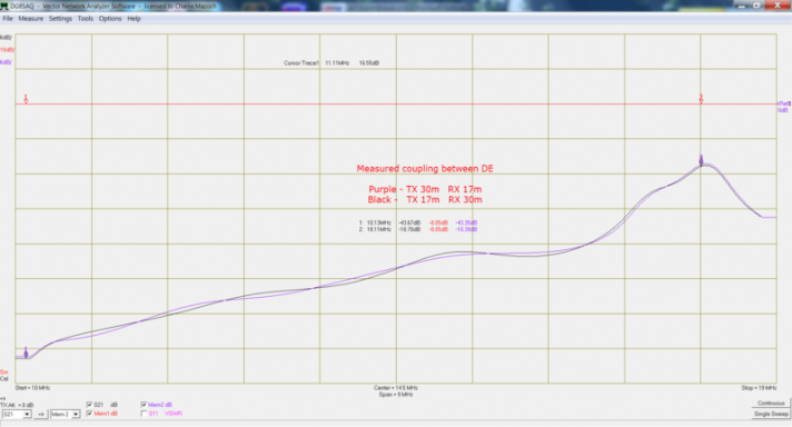
A Switching Surprise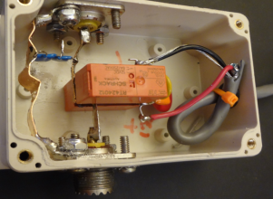
The antenna mounted in it's final position on the 40m looked good with expected SWR on both bands, based on measurements at the feedlines at the bottom of the tower. However when back at the shack the 17m beam showed 1.6-2.1:1 SWR readings which were much higher than the 1.2-1.3:1 measured in the field. I really had no idea what was causing the issue until I happened to later hook the 30mm feed line up to the DXE switch while looking at the 17m SWR - and noticed the SWR jump up! Then I remembered the DXE switch shorts unused antenna feedlines to ground. I had not considered that possibility when doing the modeling of the beams and assumed a 50 ohm feed line termination on both antennas would be present at all times - something the original KK1L 2x6 switch provides but the DXE switch does not. Another oops! After looking at various options the easiest solution was to put a relay in series with the 30m feed line so that when the 30m antenna was not in use, the feed line center conductor would be opened, minimizing the impact to the 17m antenna. Fortunately the Microham system comes to the rescue again making the relay control easy. After programming the Microham to open the 30m feed line "bypass open" relay when the 30m beam is not in use and then hooking that control signal to one of the unused lines feeding the 40m tower, I just needed a relay of some sort to do the actual work. 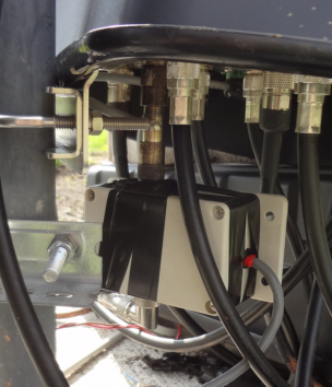
Shown here is the relay box internal construction and it's as-mounted position. It hangs below the DXE switch and is somewhat sheltered from the elements. Works great and restored the expected 17m SWR that had eluded me. |