Getting Stacks Under Control using K7EL's Current Forcing Phasing Method Download the Monostacker docs by clicking HERE The stack matching box used here is the Monostacker. It implements a switchable method of driving up to 4 beams with correct 50-ohm in-phase matching based on the current forcing method popularized by Roy Lewallen W7EL. The Monostacker is essentially a collection of relays and a few lengths of quarter-wave feedline switched into the mix driving the right combination of feedline lengths. The system is single banded - hence the "mono" in the name - but given the entire station here is built out of monoband antennas so it's a good fit for what is on the towers. Popular alternatives use phasing transformers and in some cases discrete L/C to do the similar thing. A requirement for the phasing to work right is that the feed lines to individual antennas are the same length and that the lengths are odd quarter-wave multiples of line. I did not build the feedline lengths in advance preferring to use hardline runs up the tower and then bumping the runs to the correct magic length by adding a bit of padding feedline at the base of the tower. The needed padder length was determined by measuring the electrical length of the run from the base of the tower up to the feedpoint for each antenna using TDR. I chose to put the matching box at ground level which simplifies the build and maintenance end, but it comes at a cost of longer runs to each antenna which I have mitigated by using big hardline runs up the tower and making as much of the Monostacker interconnect out of hardline as well. The big boys tend to put the stack matching stuff up on the tower to minimize the feedline runs - but knowing my luck I would probably encounter a failure and have to climb a tower to do a swap in the middle of winter - no thanks! THE MONOSTACKER BUILD 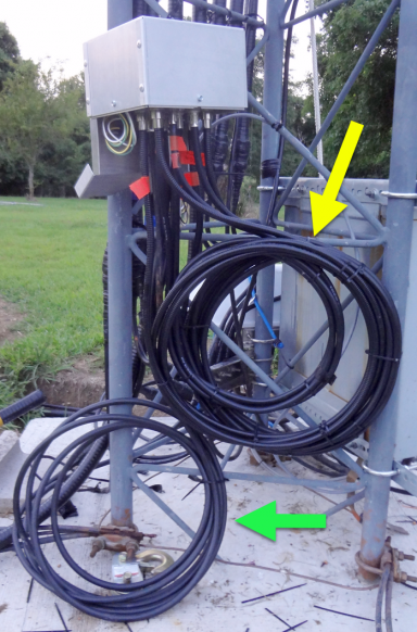
The Monostacker PCB (shown below) is housed in a small aluminum box. The impedance matching magic is accomplished with two lengths of quarter wave 50-ohm, one of 75-ohm and one more of 35-ohm coax. These stubs are nicely bundled and mounted against the tower as shown at left (yellow arrow). The padder lengths (green arrow) are laying against the tower while I check out the system. Once checkout is complete I will add those to the others leaving a less cluttered set of wires. There are 7 control wires plus ground that drive the various selection combinations. 4 lines select one or more of the 4 antenna combinations. And the 3 remaining select one or more of the quarter wave matching lines. Construction was straight-forward although quite labor intensive with respect to fashioning the aluminum face plate with the SO239. I am told that DXE may offer this design in the future so guys wanting to use a similar setup will have an easier go at it. 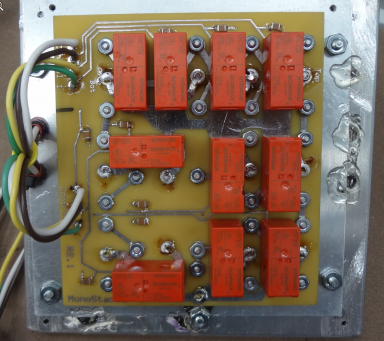
I built the 4-antenna version of the Monostacker. There is also a 2-antenna version which I used on the prior tower build which had more basic 20m/15m 2-high stacks. Of the 5 years the 2-antenna versions were in the field I never had a failure which is amazing given the amount of abuse they suffered under what was a terrible control setup in place at the time - and about 30,000 RTTY contest QSO. The business end of the Monostacker is the side with all the SO239 connectors. 8 are for the matching stubs, an additional 4 connect to the antennas and the remaining one is the output which runs over to the DXE coax switch. 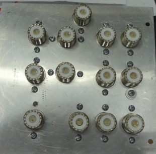
STACK CONTROLControl of the 7 lines for each Monostacker is managed through the Microham SMD system. Selection of the antenna combinations is via a set of 4 push buttons on the front of the SMD. Instead of having a bunch of discrete rotary switch positions run off a diode matrix + rotary switch which is the usual control method, the SMD let's me pick the combo that I want by pushing one or more of the buttons at the same time. The SMD configuration flexibility is completely programmable so it's easy to customize for each of the unique antenna configurations here. It also prohibits invalid choices by the op. For example there is no 4th 20m antenna installed at the moment so pushing the 4th button in any combination results in a beep from the SMD letting the op know he's trying to do something not allowed. In the case of the 20m antennas, here's the combinations I can select from. - Top rotating 6-element 20m beam
- Fixed on EU 6-element 20m beam
- Fixed on SA 5-element 20m beam
- Top 2 (feed in-phase as a stack when the rotating antenna is pointing to EU)
- Bottom 2 (beaming EU + SA)
- Top + SA (so I can beam both JA or OC + SA for example)
- All 3 (for a stack pointing at EU + SA for example)
When the stack is not in use, all the antennas are grounded providing one more path to ground for lightning should it come my way and make it past the other discharge paths. Note that I only am using 3 of the 4 antenna positions on the switch and that leaves me an unused port for some other antenna if needed in the future. While there are a lot of wires involved in this setup, it compensates in being completely flexible especially when matched with something like the SMD which can take full advantage of the granularity. Here's what the SMD display looks like at the op position. The graphic under the yellow arrow shows that the top two antennas are selected - the top rotating and the mid fixed-on-EU (hollow box signifies an idle antenna). The 260 number shows the top rotating antenna is pointing to the west at the moment. And the green arrow graphic reflects the relative compass headings of the two antennas.  THANKS!I want to thank W8WWV and AC6LA for their prior work on this and for answering my many questions on this and other projects over the years. And to the unnamed gentlemen who have provided me with some key materials used in the build - I am very grateful for the assistance. |