 A Reminder From Mother Nature A Reminder From Mother Nature
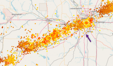
A slow moving lightning storm rolled into the area about an hour before the start of the 2019 CQ WW RTTY DX contest . The storm was moving almost perfectly inline, from the SW to the NE and crawling along. I knew it was going to be trouble for the contest but hoped it would stay off to the NE of my QTH (blue arrow on the live-lightning strike map at right). I did not know how much trouble it was going to be in the end. Ran the first couple of hours of the contest with QRN levels growing, at the same time keeping an eye on the lightning strike locations. Eventually strikes were reported within a few miles and I had to shut down. Unfortunately due to the pace of the storm, no more operation was possible until the next day. An Inventory of Damage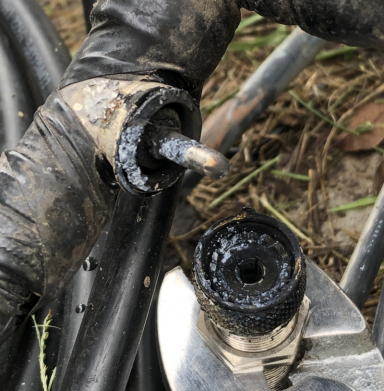
When the storms finally cleared off the next day and I could start again, I knew something was wrong when the 160m and 80m 4sq SWR was sky high. And the HiZ array was silent. Little did I know there was more to come. I could not confirm the problem with the 80m 4SQ given that another storm was rolling in and we still had heavy rains - it took a couple of days to find out the full list of problems. In the final analysis, the following list of damage were found: 1. 160m matching net - connecting wire blown open 2. 80m 4SQ had a faint smell of fried components 3. The HiZ array was drawing a lot of current and also had the smell of fried guts 4. Discovered later - damage to the Green Heron 40m tower rotor controller
5. Blasted coax-T connector on the 40m coax stub (see picture, above)
6. Discovered later, a problem with the 40m rotor controller Replacing the 40m stub T connector on the 80m feedline was easy to do but did not restore 80m operation. Things went down hill from there. The CQ WW RTTY contest for this year was clearly a bust with no chance of placing anywhere near the box. The good news is that I got a lot of sleep that weekend! HiZ 8-Circle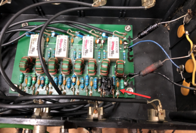
In the field, the HiZ array box was warm to the touch - odd. Checking the current drain showed it pulling about 1.7A vs. about 700 mA in the normal case. I disconnected the antennas and other lines from the unit and pulled the two boxes as well as the phasing lines out for a trip to the bench. When I got the lid off, it was clear that a highly technical diagnosis of "crispy fried guts" was confirmed. I talked to Lee at HiZ about what I found and he suspected that there would be antenna buffer amps showing shorted input DC block caps. So a later trip out to the field to pull those was needed as well. What I think happened is that a nearby strike (either transmitted through the ground - or directly to the tall 40m tower through which the HiZ feedline is routed) caused the buffer input to see a much higher voltage than the input blocking cap rating of 25V causing the short. Once the cap shorted, the supply back at the controller tried to feed the shorted buffer's endless current demand, eventually causing the small 1mH chokes in the controller box to overheat and internally short. That's what the discoloration on the board is from - the cooking inductors. HiZ Repairs & Hardening- Antenna Buffer AmpsIn checking the buffers, one was dead (with a shorted input cap as Lee predicted) and another one buffer showed blackening of the input cap however it remained functional. The OEM DC block cap is a 25V 1 uF tantalum type which has excellent low frequency response but in my experience tants do not play well with over voltage conditions. I replaced the cap and checked functionality of the buffers - all good. By way of hardening the buffers against future lightning, I added 4 items to each buffer (yellow arrows): 1. A 75V GDT across the input. The inputs of the buffer are shorted when the system is powered down but it normally runs 24x7 - and has been that way since I first put it up in 2011! The GDT would cover the case of a big spike on the antenna side, hopefully protecting the input.
2. Replaced the 25V/1uF tant cap with 2KV/0.01 uF ceramics. There is a slight low end roll-off from this change but it was only toward frequencies below 160m - the 2KV input cap would be much more robust going forward.
3. Added an 18V 1500W TVS diode across the supply lines behind the bias T. There is already a MOV across the supply line but a TVS has a much more drastic clamp chareristic and TVS diodes do not have the degradation effect that a MOV can develop over time.
4. Added low C, small 15V TVS SMT diodes across the coax feed line. TVS diodes seem to come in two flavors - big power capacity and with that a massive internal C, or micro-sized SMT types with only a few voltage options but with a much more reasonable 1pF of C. If the line gets hit again, this is likely to be the sacrificial component.
5. Shown lower on the page, added a a remote switching option. The Microham SMD system now drives a relay which feeds out to the site. That relay signal kills power to the array when it's not in use by one of the rigs in the shack meaning the system is automatically powered-down at any time where the array is not actually being used for receiving. That brings the built-in antenna side input relay into play as well, serving to clamp the antenna to the ground rod when unused. 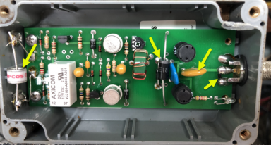
The array output runs through a final amp that is in the same sort of box as the buffers but has a F-connector in/out. Similar treatment was given to that unit as what you see here on the buffers. Additionally, modifications were made to that unit to feed the PS directly and not needing to use a bias-T arrangement which is my personal preference. HiZ Repairs & Hardening - 4 of 8 SelectorThe HiZ Pro 4-8 Circle is a set of interlaced 4-square systems. An intermediate box selects between each of the two sets of 4 antennas based on one of the control lines, and that set of 4 is fed to a separate box which has the phasing circuitry and direction selection. The box also provides the bias-T function on the PS end which is what all the inductors along the bottom of the board are for. Hardening this box involved a number of changes. 1. The OEM system does not have any built-in fusing and to improve field diagnostics capability, I added separate fuses to both the switching control line (yellow arrow, middle of page) and the PS feeding the relays (red arrow). These are slow-blow types of about 500mA capacity. I chose slow-blow because I wanted to avoid replacing soldered fuses should I momentarily touch the DC carrying buffer feedlines to ground. I assumed that in the event of a strike, the voltage and thus current would spike resulting in a fast blow under those dire circumstances despite the "slow blow" type. By looking at which fuse was later blown, it would help to unravel what may have been whacked in a subsequent event. 2. Added similar tasked fusing to the PS line feeding the bias T (green arrow). On that line there is also a HV bypass cap added for good measure and another TVS diode to clamp it. 3. The blue arrows are an additional set of TVS diodes from ground to the PS input and another one to the control line. HV bypass caps added there as well. 4. Not part of the hardening process but also implemented are some small R/C snubbers across each of the relays. When changing direction it helps cut down on the switching spikes observed in the radio (see top arrow pointing to one of the RC sets). The snubber rounds off the waveform and reduces the HF energy as a result. 5. The most obvious change was to swap out the inductors with ones that could sustain a buffer amp short and not self-destruct under sustained shorted-buffer conditions. This is somewhat overkill given the added fuse, but we ARE hardening, right? I found some SMT types that were shielded and rated for about 700 mA of constant current - but they were quite a lot larger so the total count was split with half mounted on each side of the PCB. That's what the small gray colored items are below, indicated with the orange arrow. The inductors are Coilcraft MSS1260-105KLD. 
6. The 2KV 0.01 uF DC blocking caps on the bias T were replaced as well with the same HV ceramics used on the buffers. See the bottom of the board below, interlaced inductors and blocking caps. 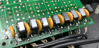
A couple of other improvements were implementing the previously mentioned remote power switching (blue relay on the PCB near the top of the photo below). Wires are sort of a mess but you can make it out clearly. The wood mounting board holds a terminal strip that serves as a convenient tie point for the 3 control lines, +15V PS line, and the "PS-on" relay control line that feeds from the shack. Each of these lines has an added TVS and bypass cap to ground. 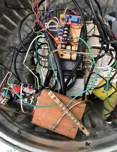
Mistakes MadeThere was not much of a ground at the antenna site. The HiZ system requires only a token 4' ground rod at each antenna and that's located a the end of each of the buffers - meaning there is a lot of wire and thus a lot of L between the controller and the antennas. Definitely not a great ground, especially in mitigating ground bounce from a strike. To improve the ground, a trio of 8' ground rods were added. One rod right at the base of the trashcan container that holds the controller stuff, and two more out about 15' located N and S of the center rod. They are interconnected with #6 wire from the junkbox. A separate #6 wire runs up from this ground joint of the 3 rods, up to a brass tie-bar in the trash can (shown above, on the wood block - bottom of the photo). A #12 jumper runs over to the PS regulator (bottom left) and to the array terminal block (top center). A short jumper from the ground rod junction to the shield of the feedline is also made, on the far side of the final amp where the feedline runs back to the shack. In retrospect it seems odd that, while I had installed serious grounding at the two towers and at the shack, I somehow managed to overlook possible problems with the 850' run of wire between the shack and this RX site. Worse, that feedline runs physically through but is not electrically connected to any of the 3 ground systems. Oops! I can just imagine how that run of ungrounded wire served as a nice long wire antenna soaking up all sort of strike energy. It's really a wonder I have not encountered a problem before today with that setup. 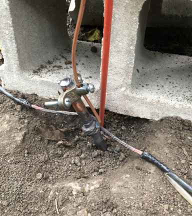
With these repairs made, the array is back in action and working like it was new. A lot of work but I am pretty sure that the next time I have lightning, mother nature will have to up her game at least a little bit to do damage to the system. Having written that, I am reminded of an old advertisement about it being not nice to temp mother nature or something similar. Knocking on wood here, just for extra luck. 80m 4SQ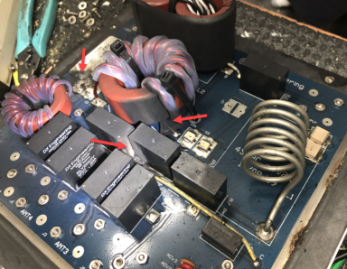
The 80m 4SQ was behaving oddly. It had high SWR on all of the individual directions, but SWR was fine on the OMNI mode. The OMNI circuitry is located before the directional stuff and I was able to make a guess that there was damage to the directional side of the box, and that the individual verticals and their feeds were probably OK - if not, the OMNI mode would definitely show it. That proved to be the case. With the controller back on the bench, the oder of fried circuitry was strong even with the nearly water-tight cover still in place. When opened, the damaged seemed every where. Circuit board arcs, more arcing between two relays and a literally blasted SMT cap jumped out right away. 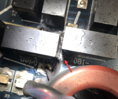
Shown left is the arc damage between the two closest relays and the circuit board. 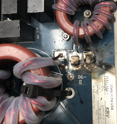
Close-up of the two caps with damage - the right cap is missing part of the body and the one at the left is cracked. I replaced the box with a spare controller which brought the 80m 4sq back into operational condition. The fried controller was sent back to DXE to see if it can be rescued. 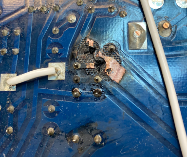
This photo courttsey of DXE when I sent the unit in for "repair." Uh, guess that's not happening... 80m 4SQ Hardening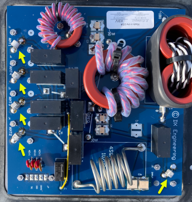
With the center of the array being a 130' high vertical, I doubt that lightning will ever made a direct strike onto the 80m 4SQ elements. However I can certainly see a case of induction between what are two parallel conductors albeit spaced by 50' or so, and suspect that the damage seen above was a result of that kind of event. I thought about putting spark gap GDT at the base of each vertical but decided not to do that given the ground wires of these 80m verticals are of lightweight #22 wire - meaning they are even more susceptible to being blown to bits in a surge than the 160m tower's 18 gauge wire. A better solution seemed to try to short the induced surge to ground by mounting GDT on each of the 4 antenna feeds at the controller as well as on the feedline run back to the DXE switch. The DXE controller layout makes this easy to do on the exposed back side of the PCB and only takes a few minutes. This will help to shunt any future induced currents to ground via the 160m ground screen and newly added ground rods (explained below). A more robust solution would be to put something like a Polyphaser and a barrel on the bottom of the box and use heavy gauge wire to tie that over to the ground - but that was a very expensive solution by comparison ($5 for the soldered-in GDT vs. $250 for the external Polyphasers & gender-matching barrels. Shown at right are the 5 locations for the GDT. On the ANT 1-4, I used 800V GDT, and 1KV on the feedline. I don't think it's very critical as long as the GDT contain the voltage so that arcs internal to the relays don't occur. See the comment on the added grounding below in the 160m tower section improvements. 160m Tower 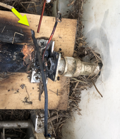
The 160m vertical is shorted at the 2x8 DXE antenna when not in use so I suspect that relay and the 325' feedline was hammered by the strike, but it remains operational now with no apparent problem. It's also possible there was some arcing in the matching net but I did not notice it. The damage to the 160m tower was minimal. A small gauge wire was used to jumper a center conductor from a SO239 over to a series matching cap and it blew - an easy fix. No other damage was evident. Note that the burning shown in this is from a prior torch use to do a field patch of wire, and not from this lightning event. There is some carbon scoring dust on the connecting wire (visible in the photo) but nothing else. Retacked that wire and the 160m antenna was back in action The matching net was intended only to serve a temporary function but it's worked so well I have never got around to fixing it. I should as it's apparently a nice shelter for mice as well as a fine matching net. A guy told me once that the meaning of "temporary" to a ham was actually "until it breaks or falls down" - I think he was right. 160m Hardening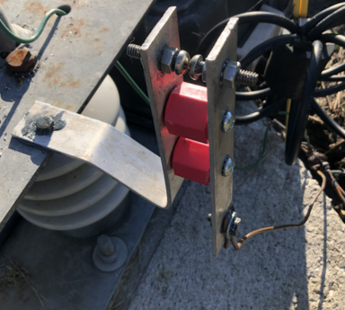
The tower is of an insulated base type and to help contain the voltage rise at the base, I added a spark gap shown left. The gap is adjustable via the two SS screws. A short length of #6 solid runs down to the ground network. 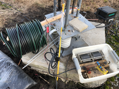
An overdue addition was this 80m half-wave shorted stub. The 80m 4SQ is minimally disturbed by the presence of the 160m vertical in the middle of the array, however that depends on a good grounded electrical connection on 80m. It's something I had intended to add for a long time - based on model results. The 160m feedline is grounded back at the 2x8 switch but with the long run distance, I would have to measure it which I ended up not doing. And that would have two different loadings based on the DXE switch relay status. With the stub across 160m antenna directly at the base, it provides a full time 80m low Z function, is invisible on 160m, and offers a DC path to ground for static. It would provide the first line of defense in the event of a strike and for that reason was built from some serious 5/8" CATV hardline. About That Ground...For some reason that I cannot comprehend now, I never provided a lightning-purposed ground for this tower! I seem to have assumed that with 80 insulated #18 gauge radials buried in the ground, the cap coupling afforded at lightning frequencies would be low enough to provide a wide dissipation path. In retrospect that seems a stupid conclusion because the more likely scenario is that the lowest Z radials will be blasted along the length, perhaps resulting in a degraded ground system of unknown condition. The fix of course is the usual - heavy interconnecting wires and multiple ground rods. To that end, I added 12 rods spaced out 8, 24 and 35' from the base, connected with some #4 and #6 wire I had from the grounding rod work with the other towers. The wires are torch-brazed using silver-bearing rod stock which can be welded with MAAP gas torches. The perimeter ring at the tower was originally a single #6 solid and I added an additional rig of #6, also bonded along the way at several points with the same brazing method. Not a perfect ground, but definitely a big improvement over what it had been in the past. Green Heron Rotor Controller 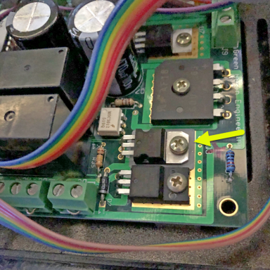
I did not initially realize that the Green Heron controller on the 40m tower was damaged until I noticed that the rotor seemed to turn very quickly - and that it tended to over-run the selected direction by 5-10 degrees. Two things that definitely were not happening before the "event." Comparing the output of the two GH controllers in the shack (the 20m tower operational one and the 40m tower suspect one), it was clear the PWM function was not working. The controller was not ramping up and down the rotor speed, but instead was slamming the rotor with full power with each turn instruction. And what I was seeing as overshot was due to the rotational inertia of a lot of big antennas straining against the braking of the SPID BIG RAK's worm gears as it fought being spun by the antennas. I cannot imagine what the forces were on that gear set... Fortunately nothing seems to have been damaged. The GH guys were very helpful in identifying the likely culprit which turns out to be a FET IC (yellow arrow). Replacing that part was quick and easy, not even requiring the PCB to be pulled from the case and restored proper operation. 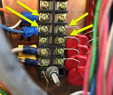
More MistakesI was surprised at the GH controller damage because it's well clamped against just such an eventuality. There are big MOV in the field, at the shack entrance plus the internal TVS diodes clamping the output from overvoltage. Well upon close inspection, there were those MOV mounted, but in both cases they were not actually working as intended - due to installation errors! At the tower I found this odd connection, shown left. You can see the MOV are connect one-terminal-off from correct meaning in this case one of the rotor pulse sense wires was left unprotected. Oops again! And back at the shack, I found the MOV properly across the pulse sense line, but the ground side connection of the MOV was not screwed down tight making them worthless. I corrected both of those. One observation when checking this out was that the TVS selected for the output is a bi-directional 70V type. The max voltage of the output FET is also 70V so it should be protected, right? But it got blasted somehow. Perhaps vial the pulse line which was unclamped external to the box and that induced or found a path inside the controller - no idea really. I also speculate that perhaps the TVS may have allowed the motor line to lift high enough to pop the FET even with the TVS because the avalanche curve of the TVS - while being much flatter than a MOV - still has some slope to it. Hard to be sure. By way of additional protection, the peak voltage of the controller in my setup was measured on an oscilloscope at about 35V. So I added 38V TVS to all the external rotor wire leads on the back of each of the GH as an added clamp. And I checked the 20m tower MOV for proper installation - no problems found there. Fingers crossed! |