 6-over-6 on 20m plus 5 elements fixed on SA 6-over-6 on 20m plus 5 elements fixed on SA
The 20m station antennas are setup like this and controlled by a stack switch: Top: rotating 20m JK206 6-element/44 foot yagi Mid: fixed-on-EU 20m JK206 6-element/44 foot yagi Bot: fixed-on-SA 20m JK205 5-element/39 foot yagi The top two beams form a 6-over-6 stack when pointing at EU. As selected by Microham SMD interface which drives the stack match controller, a variety of beam combinations are at the fingertips of the operator. For more details on how the stack match setup here in the shack works, see the page on Stack Matching. The flagship antenna here is the JK206, a 6-element monster on a 44 foot 3" boom. The antenna is shown below after completion. Take note that the end tips have not been extended yet so the beam is actually wider than it looks here. 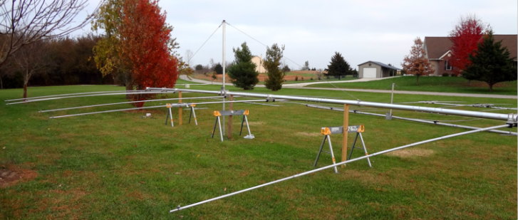
One of the reasons I chose the JK beams here was the hardware which is simply massive. And with this beam sitting at the top of 8 antennas on the tower, one of the justifications for it's choice is that I felt it would likely survive whatever storms and winter conditions Kansas could throw at it. The JK205 is a shorter 39' boom version The mast plate and truss mount are shown below. I've built this beam with a boom-mounted truss using 2-3/8 SCH-40 steel pipe which looks small next to the 3"x1/4" boom. 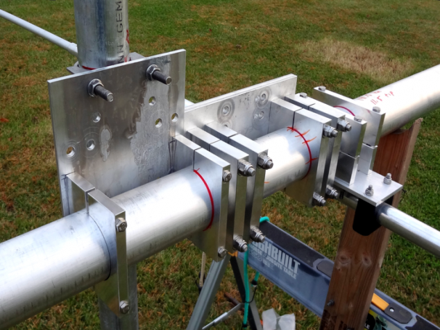
Here's a shot of the antenna as it waits its turn to be lifted up to the top of the mast. 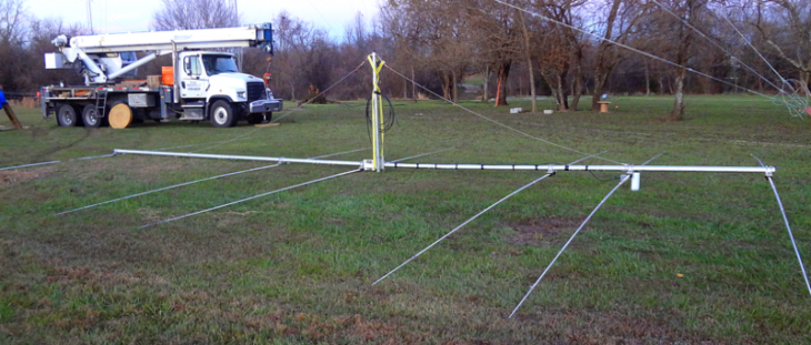
Modeling Results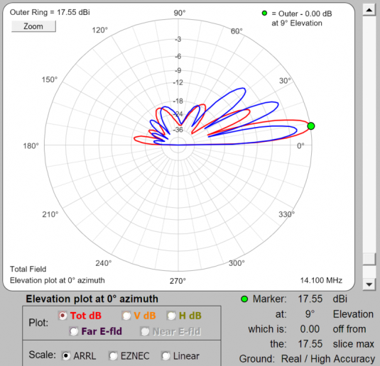
For more comments on how I use EZNEC, AutoEZ and HFTA, see the 40m Stack page HERE. Shown at left are the EZNEC/4 plots of the stack at final height. BLUE trace is the TOP antenna only. And the RED trace is the top and bottom antennas working in a stack. As with the other stacks here, all the fixed antennas are pointed to EU at about 40 degrees. The plot assumes both antennas are pointing along the same bearing. As with the 40m case, the stacks provide improvement in gain and in minimizing the antenna response to the higher lobes (in this case there are 2 above the main lobe). The back side and top-most lobes of the pattern are more or less unchanged. The bottom most rear lobe of the stack (RED) is about 10 dB stronger than in the top antenna (BLUE) but that only means if we do hear someone off the back, the DX will have an easier time of it than the west coast guys. HFTA AnalysisAs with the 40m tower, the height of the 20m beam was determined to be paramount and the combination of HFTA & AutoEZ/EZNEC analysis determined the optimal beam height under the constraint that the tower needed to be around 130' maximum. The final placement choice for the big 6-element JK was 128 feet which resulted in a 114' high tower build. 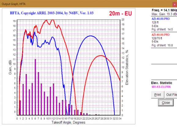
Analysis notes for the 20m HFTA case are generally the same as with the 40m case. The stack provides added gain and a wider footprint - and depending on the angle the gain is very substantial approaching 5 dB in the best case! At the same time the null point when stacked moves out to the 21 degree point which is more favorable than at the 16-17 degree point as is the case with the single (top/BLUE) antenna. 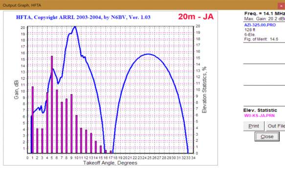
Because the bottom antenna is fixed on EU, when beaming JA we only have the top antenna (rotating) available. The bad part of this plot is that we are working against a very poor up hill condition (see the terrain plot below). The good part is that with the exception of the 1-degree spike, the peak distribution of DX across the elevation is somewhat matched with local peaks in the antenna response. In practice working into JA and to Asia generally has not been difficult. 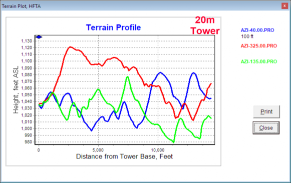
Terrain here could be a poster for The Good, the Bad and the Ugly. Off to EU, it rises only about 20 feet over the first 1/4 mile and drops at about 1/2 mile out. There are distant hilly conditions as we near 2 miles. For SA, it's about the same as EU close in with the drop off and the hills showing up closer. And for JA, it's just UGLY. Almost from the start the terrain rises extending nearly 100 feet at 1/2 mile out. YUCK! 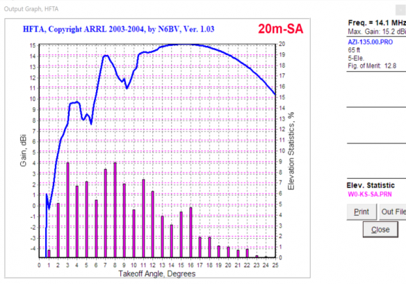
The 3rd 20m beam on the tower is a 5-element JK on a 36' boom, mounted at 65'. The height of this antenna was picked based on a compromise between HFTA results and interaction with the 20m 6-element fixed on EU beam just above it. As with the JA beam, we are lucky to have local bumps in the graph line up with spikes in the DX elevation distribution. |