
Featured in the May-June 2012 issue of the National Contest Journal. CLICK HERE to download a copy of the reprint here, coutersy of the ARRL! An introduction and overview of the system's capabilities are given below. With more complete details, including design methodology, build details and measurements, are found in the REBUILD tabs to the left. What's New in Generation 5 There were so many refinements and improvements made in the recent rebuild series, that I've decided to call this the 5th generation. Although it builds on a successful low band antennas from the Gen 4, and incorporates new antennas for 20/15/10 to take advantage of the improving (?) sunspot cycle. Fundamental changes from the previous Generation 4 array include: - Full integration of So2r operation - and antennas redesigned with So2r adjacent band interaction accomidated
- Novel use of frequency-dependent stubs to augment the prior relay-based frequency-independent decoupling
- New fixed-orientation antennas for 10m and 15m
- Complete instrumentation of all elements to facilitate fine tuning
Project Goals
- All band coverage - Provide 160-6m coverage - with directional capability where practicle.
- Use of mono-band designs where possible - simplifies optimization for that band and allows dedicated matching (hairpins, etc)
- Manage parasitics - because so many of the ham bands are harmonically related, provide some method to detune the unused elements so that they don't disrupt the antenna's pattern
- Measure - W8WWV's RVM system is used to measure each element's actual current and phase relationship as it physically exists. Antennas are initially built to rough dimensions and then trimmed to the model's indicated phase target. Once trimmed, the phase and currents (as measured by RVM) are plugged back into the model as element sources. Then the model provides a prediction of the overall radiation pattern based on actual current/phase values measured.
- Automate - array functions are automated to the extent the antenna will follow rig band selection and emulate a rotor for direction control integration with software.
- So2r - consider So2r operation in the automation, design and build to allow ajacent band pair operation (e.g. 20m/15m or 15m/10m, etc.)
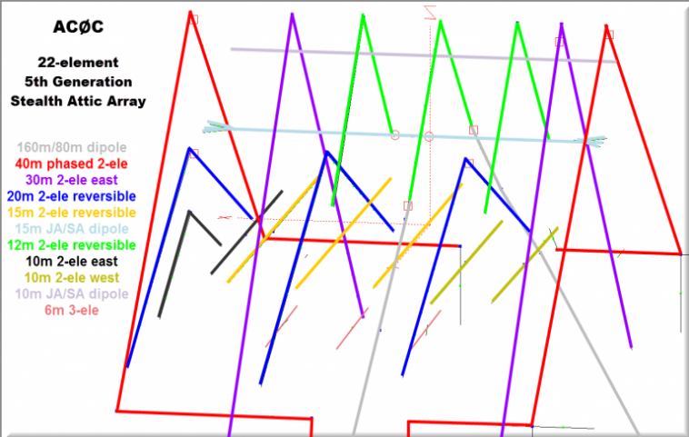
Generation 5 Array Antennas Attic Antenna "Farm Plot" Description Attic volume is a triangle-shaped space 16' high at the center, 20' along the "beam length" and 40' wide at the triangle base. The apex of the attic space is about 45' (11.3 m) above ground level. I am fortunate that the attic orientation allows the antenna boom to "beam" ENE and WNW (analysis HERE). The rear of the house slopes down and away giving an improved "east beaming" height above ground level. The attic space has only one vertical stove pipe vent although the attic floor has a full complement of HVAC and some house lighting wiring. One end of the building has a stucco metal supporting mesh that has been the source of much grief - that topic is explored in the link HERE Not included in the attic array - but a key part of the overall system - is the 160/80m receiving loop. Work Remaining - Conversion of the 30m parasitic to a phased drive reversible type
- Replace the current manual direction control on the 2nd rig with an automatic rotor emulation interface
- Add directors to the 17m dipole DE to create beam functionality
- Add matching/switching to facilitate use of the 15m N/S dipole on the 17/20m bands
Antenna Construction Highlights
80M Trap - 160M Loading Coil 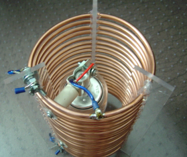
Traps are used on this driven element in 2 places. Near the apex for 12m and then again for 80m. With the traps, the antenna is resonant at 24.900, 3.540 and 1.825 MHz. Given the troubles with the prior generation traps, I wanted to ensure that the new traps were indestructible. The new design is 1/4" copper tubing on a 5" form. The capacitor is a 15KV 100 pF 5% Russian surplus unit. Hi-Pot testing of the caps showed only a few uA of leakage at 15KV. I did not measure the traps Q but would guess its in the 300+ range based on similar work. The only compromises that were made were putting the metal components within the coil and the use of dissimilar metals in direct contact. As the coils would be not used in the outdoor weather environment,I felt these were negligible factors on the overall design. After having participated in many RTTY contests, I can say the traps are performing very well indeed! 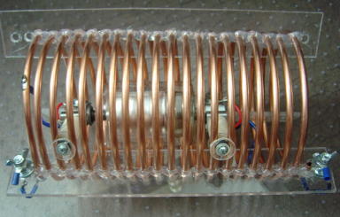
Antenna Mounted Isolation Modules Detuning of the elements not used for a given antenna is accomplished by the isolation modules of varying design. Depending on the model analysis, the function of the module is to allow the center of the dipole elements to be open or shorted by relay - and may incorporate either parallel or series connected stubs to provide frequency-dependent behavior. The 160/80/12m DE module is shown below. Ten stubs and over 50 relays are required to implement the array's many functions. 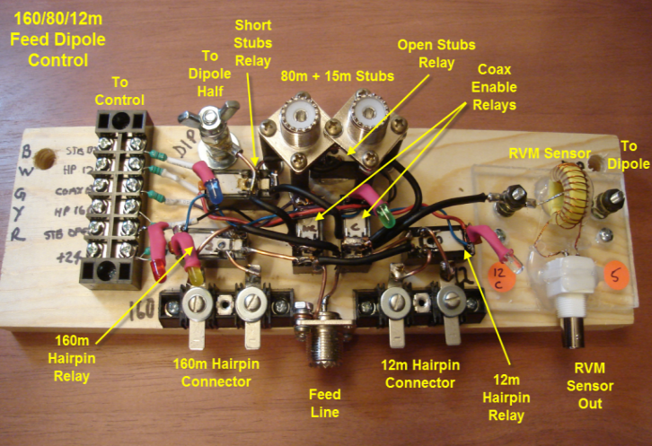
Below you can see a simpler control module, this one for the 15m director. And with a stub hanging below. For more explanation of the function of the stub and interaction with the control module, see the page on the 15m rebuild here. 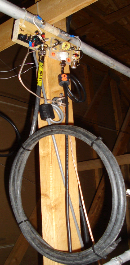
Automation - Attic Mounted Relay Switching Driver Boards There are two attic-mounted switching boards - The Attic Control board and the So2r board. The Attic Control board handles the relay-based open/short control, as well as part of the antenna feed switching. And the So2r board (described later) handles the rig sharing needs on the 40/20/15m bands. Attic Control Board ------------------------------------------------------------------------------------------------- Inputs to the Attic Control Board come from the shack. And include BCD data from the shack-mounted Ameritron automatic antenna switch controller. A seperate antenna control box in the shack (described later) provides antenna control open/short combination codes as well as the direction setting line signal . The LEDs adjacent to each connection help in diagnostics and confirm which lines are active . 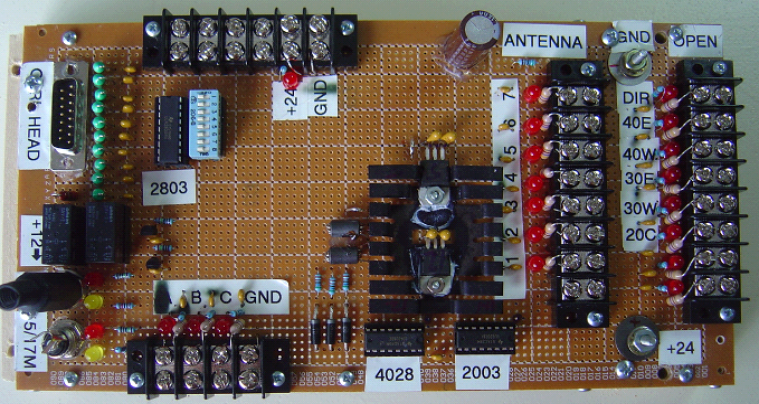
The switching module is mounted on a backing board which is secured to the studs in the attic. The backing board provides a DC power supply for the module. And serves as a mounting plate for the Ameritron 8-position antenna switch head. 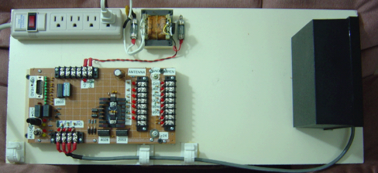
So2r Board ------------------------------------------------------------------------------------------------------------ So2r operation is implemented with one rig serving 160-6m, and a second rig capable of operation only on 40m, 20m and 15m. This board drives a KK1L 2x6 antenna switch. Inputs to this board come from the shack-mounted BPF decode driver lines. The combination of shack and attic hardware provides fully automatic antenna selection and direction switching for both rigs. More details on the attic So2r control board found HERE. 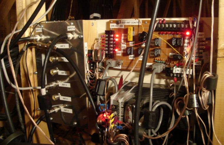
As can be seen in the photo, every control wire in the attic has a dedicated ferrite as the high levels of RF picked up by the lines can easily disrupt the 5-24v levels used by the system.
Shack Mounted Equipment and Control
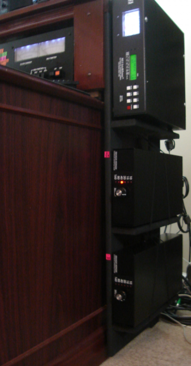
A set of 5B4AGN W3NQN-style BPF auto-switching modules in the shack provide rig isolation. Shack Mounted Control Module NOTE: Shown below is the controller as implemented with the initial single-radio model. It's replacement will incorporate this circuitry with an added 2nd rig capability to facilitate automatic direction control. The heart of the system is the control module. It's tied into the rest of the shack hardware as summarized by the topology in the drawing below. While it was constructed at the implementation of the Gen 4 (relay-only decoupling method), it's still used in the curreng Gen 5 system. Eventually, this functionality will be combined with a rotor emulation for the 2nd rig - hopefully to be completed in the off season. 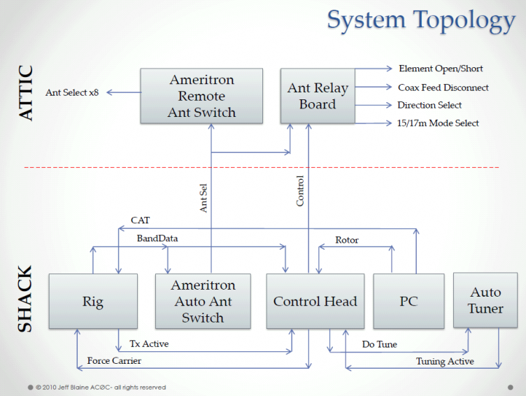
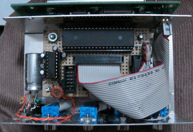
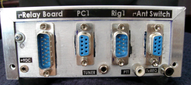
The control head is shown below. Functions are labeled. Notice that auto-tuner control as well as pulse/carrier buttons are present to make amp tune-up easy. 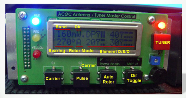
Attic ViewsA few interesting photos of the antenna is shown here. It's a bit hard to photograph what is mostly a wire-based attic antenna system. But these pictures should give you a preview. More complete details - and more photos - are contained in the rebuild sections on the tabs to the left of this page. Parts for the "Two and a Half" 10m beams 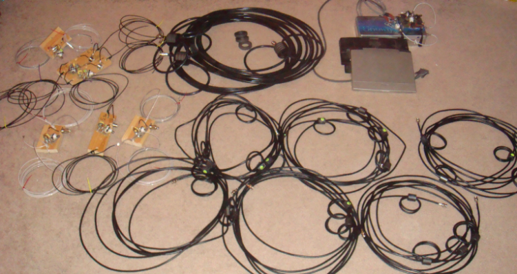
40m phased array control module and coax stubs 
View below shows (from bottom to top) the 10m E, 20m E and 40m E elements 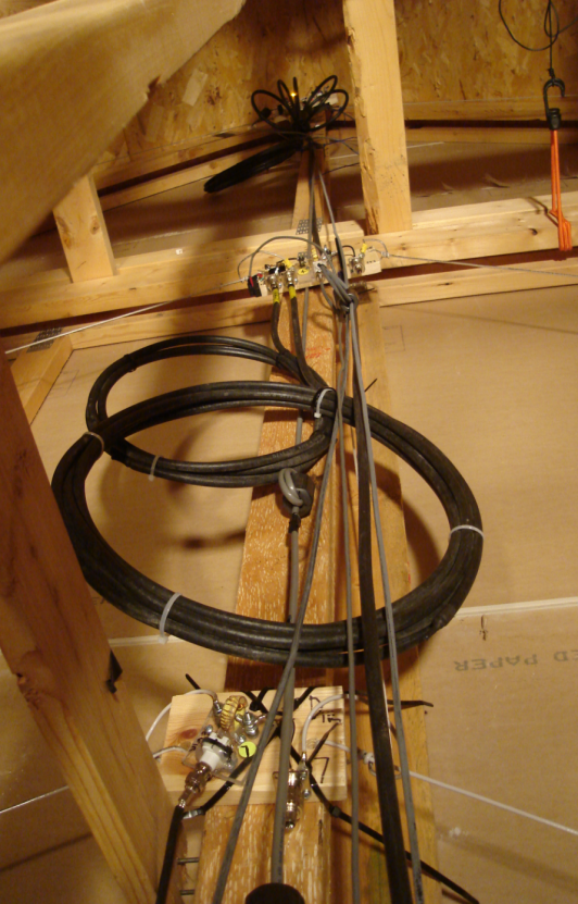 160m/80m/12m dipole control module and stubs 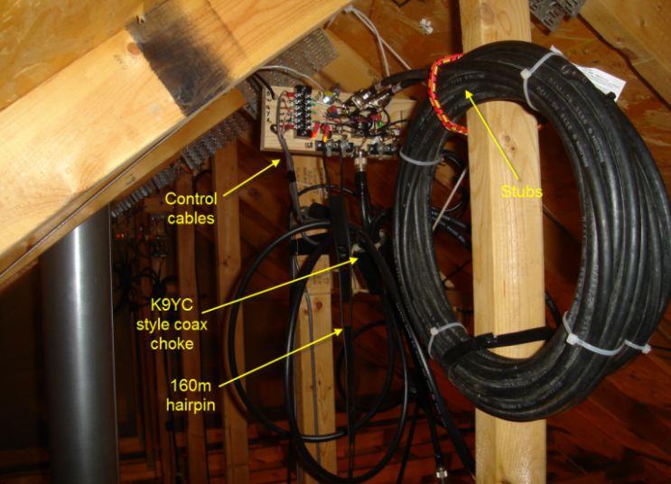
15m directory control module 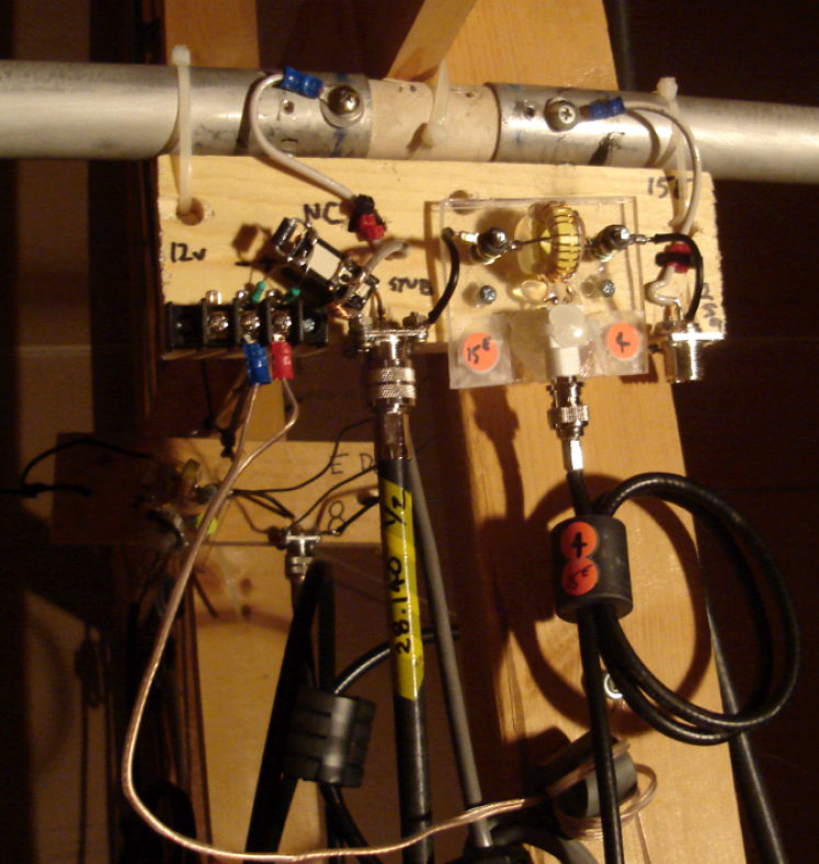
40m control module (one of two) The coil on the left is the stub. And the coil on the right is the K9YC-style coax choke on the feed line. 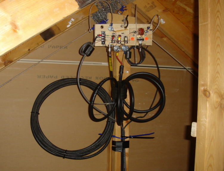
|