The 40m beam works very FB. I have no need to change it's operation - on 40m. However, as with the other antennas, some modifications need to be made to accommodate the So2r operation. Design Changes 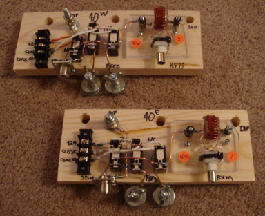 The model operation calls for a director switching matrix which operates this way: 40m: Open (both ends are driven elements in the phased array) 20m: Closed 15m: Open 10m: Closed Here we follow the use of a series connected stub to perform the magic. 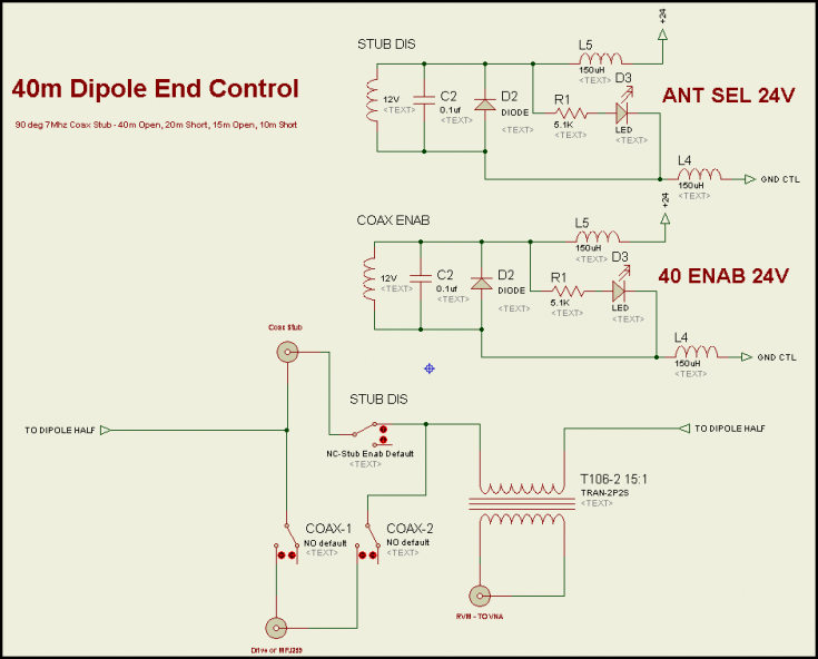
The switching is easily accomplished by the parallel-connected stub acting as shown in this Elsie plot: 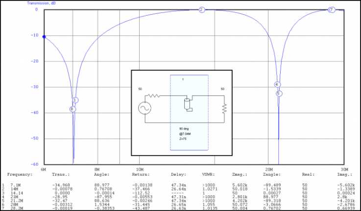
Models Models are unchanged from the prior design work. And reproduced here for reference. Note that the model assumes the 80m dipole has a 40m short. Beaming EAST 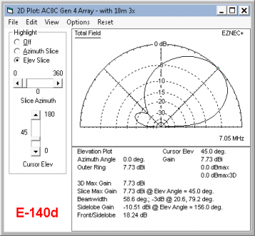 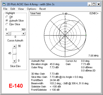
BEAMING WEST 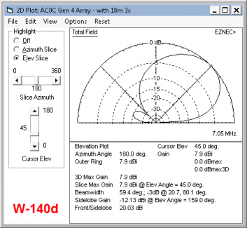 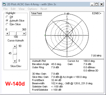 ` `
OM NI MODE - this drive has both elements driven in phase. The pattern is not exactly this clean because a formal power forcing drive is not used - the two elements are just tied in parallel and a series cap trims the SWR down to a manageable level. The mode is fantastic for domestic contests where the east/west beaming nulls tend to hurt the signal into Texas and the Dakotas. Greg Ordy W8WWV suggested it and it's usefulness was what got me to thinking about adding in a north/south capability on 10m. Thanks Greg. 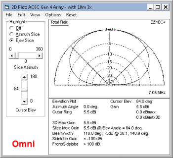 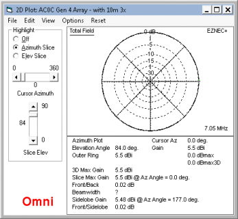
Why Is This A Good DX Antenna?Before the higher bands got hot this year thanks to some real sunspot activity, this antenna has been the anchor for contesting. I have no problems holding a frequency (with the amp of course) and the amount of DX worked on this antenna in contests is always surprising. So while reviewing the model, I also took a look at what low angle radiation strength was to be had. Normally I don't feel that a 40m antenna up only 45' at the apex - and with an average height of perhaps 38' should perform as well. But there are a couple of things that do help. First, as the diagram below suggests, the amount of power available at low angles does in fact roll off quite slowly. Here I have compared the peak gain (available at a TOA of 45 degrees) with an arbitrary low 6-degree TOA. The difference is about 12.4 db - or roughly 2 S-units. What that means is the ERP on a 6-degree is only about the difference that turning off the amp would make in a domestic QSO - something we have all played around with and have a feel for. 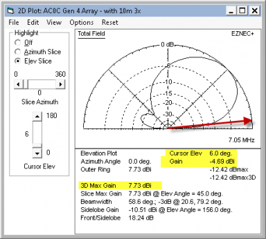
And secondly, there is a bit more help from the landscape topology. The ground actually falls off (sloping down and away) in the ENE direction of the antenna - so important for EU regional QSOs. And while there is the stucco at the far end of the house to contend with, it's far enough away in the ENE direction that it does not couple significantly and likely acts as a somewhat passive re-radiator with some finite amount of loss. This topology slope makes the antenna see an effective height of perhaps 50 feet or higher. For whatever reason, I love this antenna and it's a real great performer in all 3 directional modes. Build DetailsConstruction is similar to the 15/20m prior works. Key components shown below. This antenna is a phase-driven array, and as such, there is no center element as in the other antennas. Both ends function identically and are switched identically. Actually the switches are there because the antenna isolation is handled via switching for the WARC bands (not part of the So2r rotation so relays work fine in that role). Not shown in this photo are a couple of small LED to help provide visual indication of applied power to the relays. Directional control for the array is provided through a switching of phase lines down on the attic. See the original article on this antenna for more details regarding the antenna design. 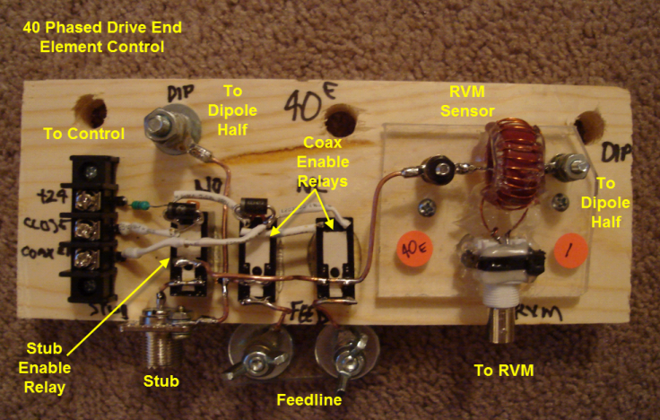
Shown here, the 40m ease element control board mounted. The coax stub coil sits on the left and a K9YC-type coax choke in the center on the feed-line. To the right is the RVM sensor line. And on the far left is the relay control cable. 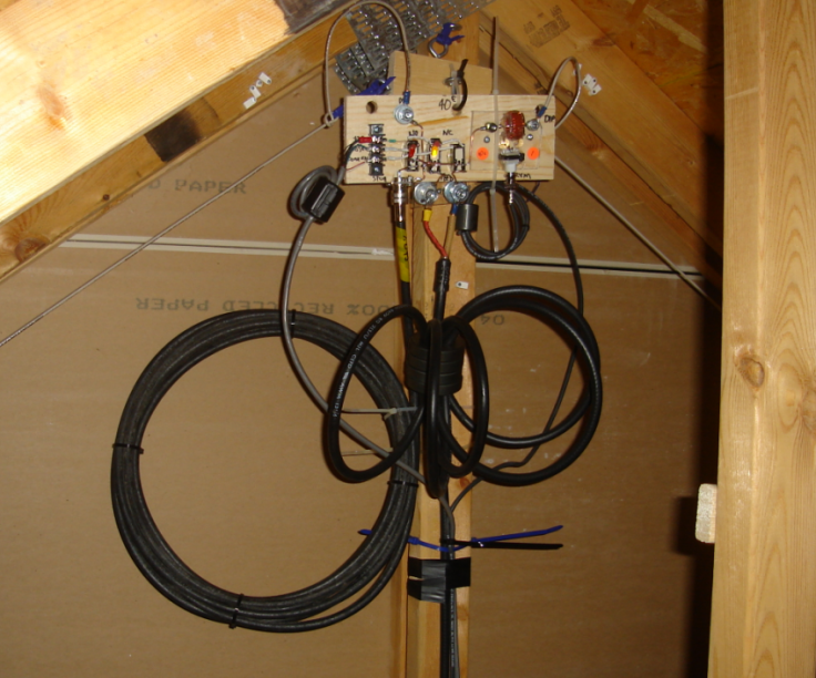
ResultsThe element phasing was checked as part of the rebuild process. Fresh RVM sensors and cables were used. Results below. Conclusion? Phased arrays are still GREAT!!! East-------- 7.000 1.42 -132 7.025 1.25 -136 7.050 1.11 -139 (plot below) 7.100 0.97 -136 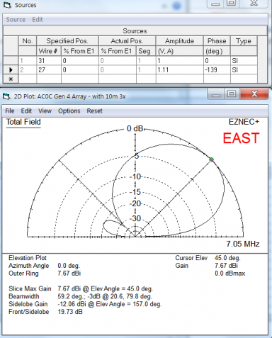
West------- 7.000 1.07 -138 7.025 1.11 -145 7.050 0.99 -145 (plot below) 7.100 0.91 -152 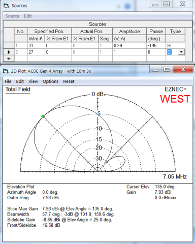
|