In the recent ARRL RU contest, the 10m dipole addition worked out very well covering the NNW route to Japan and the SSE route to South America. And at the same, the 15m beam's nulls were very evident with poor JA/SA results. What was needed was a similar dipole treatment for the 15m beam to provide some much needed side null fill. DesignThe available location for the dipole was above the 20m element apex which puts it physically along the upper horizontal rafters. The dipole is pushed up against the east wall to maximize spacing from the west side stucco wall. With only 20 feet of available "beam" length, a full size 15m dipole would not fit. So a fork-shaped capacity hat is fitted on each end to shrink the overall length to about 17 feet. 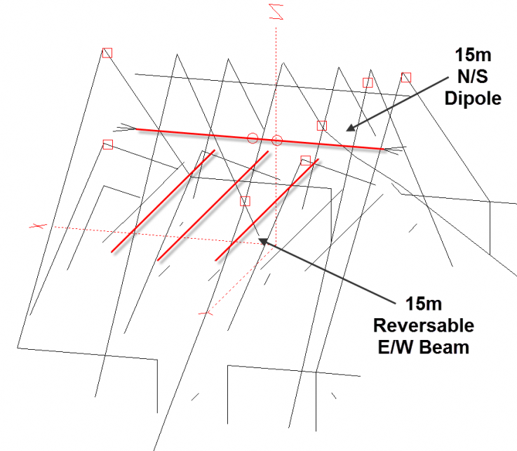
To enable the automatic dipole selection based on bearing, it's got to be tied into the existing switching structure somehow. The existing beam structure handles the east/west selection. Unfortunately there is no support preexisting support for an OMNI mode. 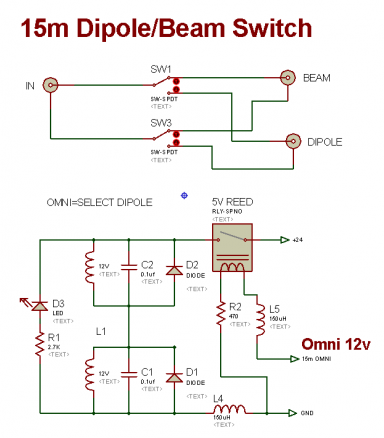
With the addition of an additional antenna switch, selection of the beam or dipole can be had via an OMNI line. The OMNI signal for either rig A or rig B is provided by the attic So2r controller. See this link for details. Model PredictionsThe AZ plot below shows the beam pattern (blue line) and the dipole (black line) in overlay. The dipole has 5db less gain compared to the beam . But on the NNE route to Japan, and the SSE route to South America, the improvement of the dipole over the beam is as much as 15db in the beam nulls. The model shows interactions with the 20m beam at -25 db or better. And close to -30 db on the 10m dipole. 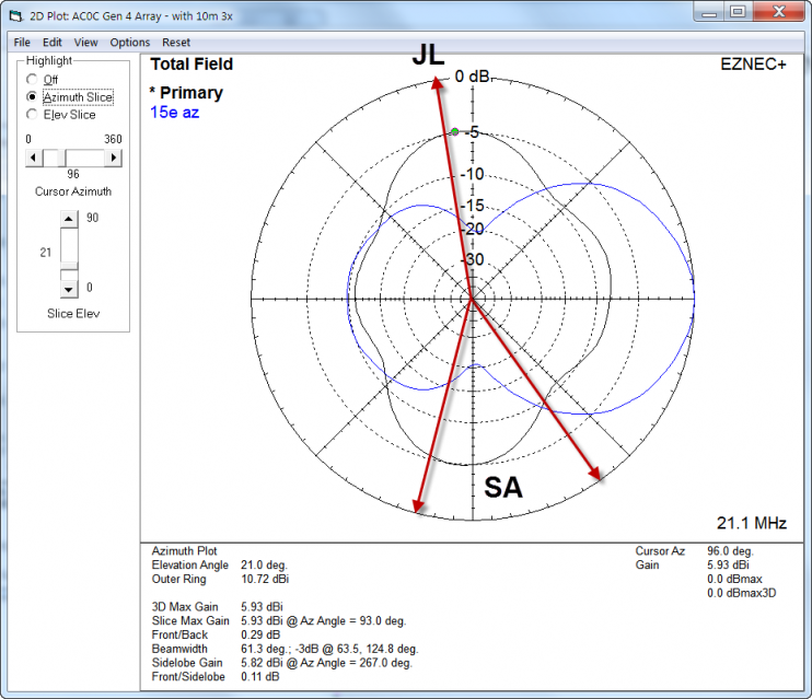
Build Details 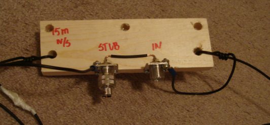
Construction is unremarkable save a facility for series stub connection. The models predicted little interaction with 10 or 20m antennas but in the event that becomes an issue, the shorting plug (shown, left) would be replaced by a stub. A 20m and 10m notch would be provided by a half-wave open series stub with the plot shown in the graph below. Of course, traditional shorting type stubs can be fixed to the drive point as well. 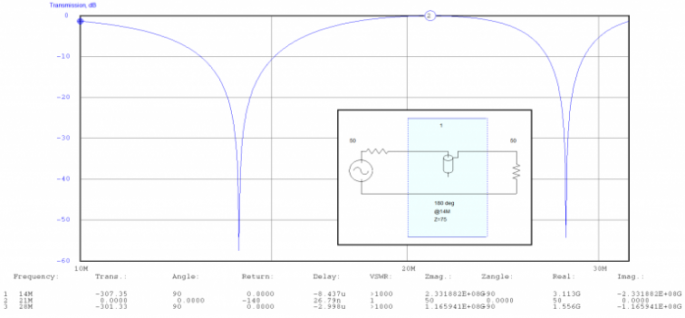
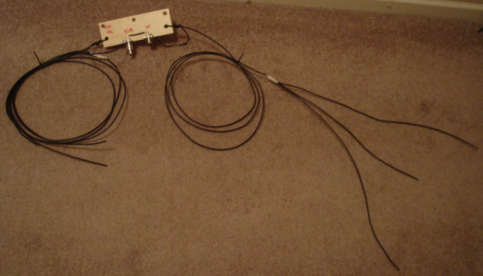
The fork-shaped capacity hat for each end is visible in the picture to the left. The resonant point of the antenna will be easily adjustable by moving these ends. 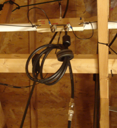
The mounting point for the dipole center was between rafters and I used a length of PVC to help support it. There is not much weight pulling on the assembly other than a length of coax. White PVC is generally a poor material for antenna construction because it's brittle in cold weather, can deform in higher temps and is subject to UV attack. But for attic work, these factors are less significant if the PVC is not put under sheer stress. The optional stub was not added at this time. The SWR is low and no further matching was needed. That also opens the door for potential use on 17/20m (with a tuner). One can never have too many antenna options... 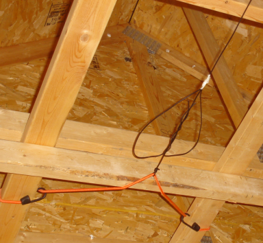
The antenna trimmed up very nicely although it was a bit shorter than expected . As a result, the full extension of the capacity hat was not needed. Shown here, a bungee cord provides the mount and gives a few inches of stand-off from the stud. The ends of attic antennas need to be spaced away from the wood to avoid capacitive coupling. Because attic wood is dry, it's a great insulator and does not provide much of an RF coupling factor. However, while the coupling is very low, it's not the same as air. So avoid running wires close-spaced and parallel to the studs if possible. And be sure to stand off the ends by a few inches. 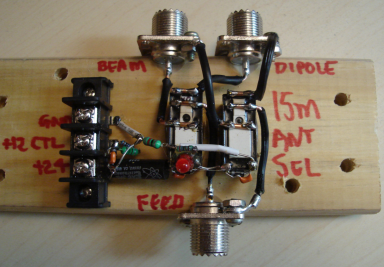
Beam/dipole switch shown here. The relays are buffered by a small reed relay to reduce current sourcing as the logic is driven by the rig select lines off the shack BPF filters. The overall switch logical function is DPDT. However, because of the frequency and current, a single relay is used for each the high and low side of the coax line to provide more headroom. The control line is driven off the attic So2r controller 15m OMNI line. |