Hardware Interlocks and Line Buffering The attic So2r control board described below is pretty simple but serves a couple of critical functions. It provides an hardware-based antenna interlock function on the 15, 20m and 40m antennas with this logic:
- RIG A and RIG B can select from 15m, 20m or 40m antennas, with RIG A (as the designated 15m/20m/40m "run" station) winning a tie.
- RIG B can (via band data decode lines) automatically select the 15m, 20m or 40m antenna when the rig is tuned to that band.
- However, if RIG A is set to 15m, 20m or 40m (again, via band data decode lines), then the antenna selection will be given to RIG A. And RIG B's antenna will open to prevent simultaneous transmission on both rigs at once.
The logic is implemented by relays who provide the interlock function as well as providing a buffering on the antenna direction lines. Buffering is important because it keeps the size of the currents flowing in the control lines from the shack to the attic low. And low currents result in smaller audible "pops" in the receiving line as the antenna switches direction. An additional So2r control head will be put in the shack later to provide a bit more interlock function (like setting transmit-inhibit) when same-band operation is detected. However, I wanted the basic functionality to be implemented such that a failure of mal-function of the shack mounted So2r control head would not affect the basic protection. I had nightmares of RF getting into my shack mounted So2r control head and my rigs transmitting a KW from one to the other! Design The design is simple. The usual concern of high local RF levels remains and is addressed in the board with a LC filter on all I/O lines. Power from the board comes from the main attic power supply. One aspect of the design is that it is fully stand-alone capable with respect to 15m/20m/40m antennas. While I have not had a semiconductor failure on the primary control board, that system is more complicated. This board provides redundancy via rig A on 15/20/40 at some level, serving as a backup to the rest of the system and for rig B. This is a second revision of the board - to add 15m capability to the earlier 20m/40m bands, an inverter for the direction line, a buffer for the 12m hairpin switch (not part of the So2r but convenient to add while the board was on the bench) as well as prewiring an extra 6 unused shack to attic control lines for future needs. Click on the schematic to download a high-resolution PDF copy. 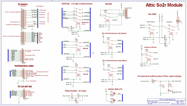
Build The board is built in a similar fashion to the main relay control board - a vector-board-style breadboard mounted on a wooden structure for strength and depth. Terminal blocks and the DB-15 allow for easy removal - the attic is a bad place to perform board repairs... The board is over-sized to allow room for some future idea if it comes up - and only 7 of the DB connector's 15 I/O are used. An unused relay socket is in place. And a dual set of 8-conductor cables has been run up to the attic from the shack - this board will utilize only one of the cables; leaving some spare capacity in place there as well. For the simplicity of the circuitry, the board is mechanically more complex than one would expect but this build style is helpful from a physical strength standpoint - and with the LED/labeling, easy to troubleshoot even after some months have passed and one has forgot what the configuration was initially. The LEDs are of a high brightness variety and will show some visible light when exposed to RF on the supply leads. This has turned out to be a very convenient assistant for identifying RF on the control lines as the attic lighting is turned out, the rig + amp is keyed with the help of an assistant - and then I look for which of the LEDs are lighting. Adjustments in the wiring or ferrite chokes is made until the LEDs no longer show visible light. This does not address common mode "board level" bounce overall but it's proven to be a workable solution in the context. 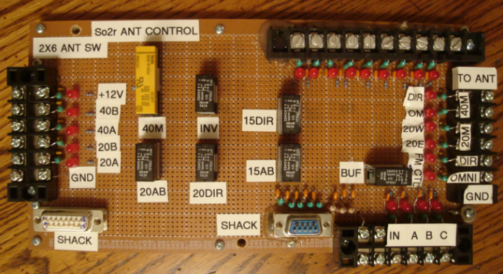
Wiring is point-to-point using wire-wrap techniques. A few of the components are solder and connected via their leads (mainly the I/O filtering and LED). 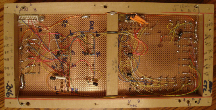
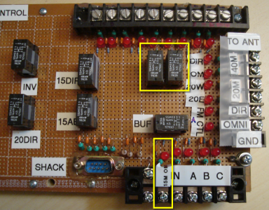
One more subsequent modification was made to accomidate the 15m OMNI mode required pulling the board one (hopefully) last time. The modification was a bit more complicated than I thought it would be at the outset. Including the the coax switching board, a total of 5 relays were needed. On the attic So2r controller, the relays (yellow boxed area) are enabled only when one rig has 15m selected, and then it routes the OMNI A/B line based on which rig is asserting 15m operation. See the 15m beam and dipole pages for more details. Sidebar: Taming Relay Induction Currents with a Snubber In this installation there are about 50 relays. And each time a relay is charged and discharged, the relay lines can serve as antennas for radiation of the spikes. By far the more troublesome of the two is the opening of the relay. When the connection to the supply is opened, the magnetic field collapses and a negative going spike many times the supply voltage can be induced. Typically a diode clamp is all that's needed to prevent the undershoot. In looking at various combinations of RC, the relays on this board responded very well to this snubber circuit. 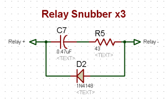 The snubber components (inside the yellow ovals below) are mounted on right at the relay coil lead connections on the socket. 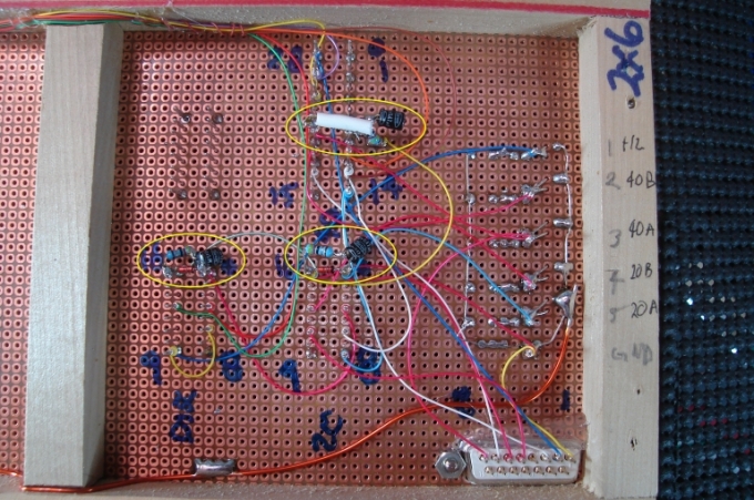 The white line shows the undamped relay line when engaged. The yellow line shows the impact of the RC. The slew rate is roughly the same but the severe overshoot is damped. 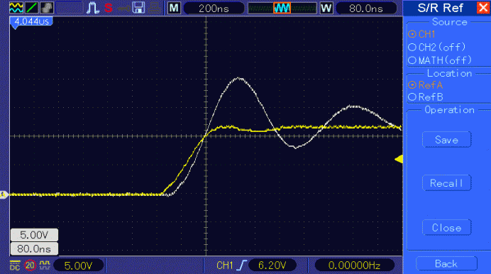
The white trace in the plot below shows the severe negative spike induced into the relay line upon relay opening. The yellow line shows the effect of the diode (clamps the gross undershoot) and the RC (slows the decay rate). 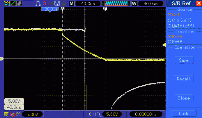
The result of this snubber should be less spikes induced into the control lines. And less "popping" QRN on the shack's rigs. And less QRN is always a good thing. --> Special thanks to Larry Benko W0QE for his suggestions on the use of snubbers - and for advice on many other parts of the attic control boards and switching. | 