 For this SO2R implementation, a dual-ported antenna switch was needed that would allow the run station antenna access. For this SO2R implementation, a dual-ported antenna switch was needed that would allow the run station antenna access.
The usual solution for this is the popular Six Pack switch. But given the nature of this project (meaning the plan was in flux), I wanted something a bit more easily configurable. The KK1L board was the perfect solution. KK1L Web Site: http://home.comcast.net/~kk1l/kk1l_2x6switch/ Why the KK1L Switch?There are a few technical points about the board which set it apart from the other projects I found on the web. First, the advertised port to port isolation was excellent at 60 db. Next, the SWR (return loss) was very low even at higher frequencies. These two specifications are not often listed in other project's write-up; and they are important for SO2R isolation operation where leakage between antennas can be compounded by leaks in the switching gear like this antenna switch. And finally, Ron had a complete, well documented design - with very importantly an excellent PCB - ready to go. Ron had a board in stock and a few days later, it arrived in the mail. One thing that makes this project a real joy is pre-prepared order lists. One click on the web site pulls up a complete parts list from Mouser. Click one time and it loads the parts list into your shopping cart. Very slick, Ron! While it was not used in my SO2R project, Ron also offers a nice dual-head band-data decoder with lockout logic PCB. And of course, the Mouser parts listing. Switch ConstructionThe bare PCB shown here in this stock photo from the KK1L web site: 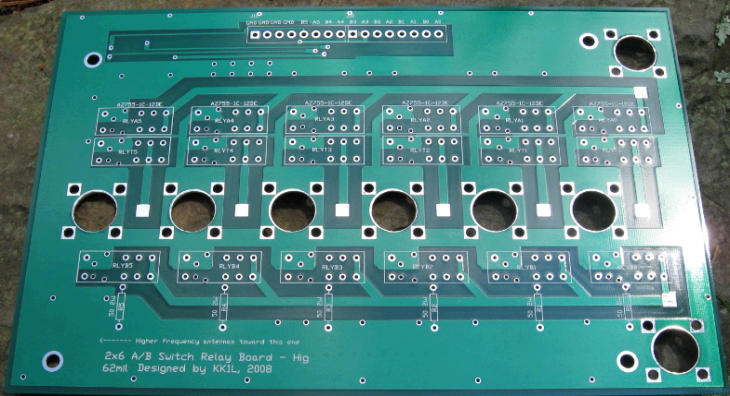
Assembly was simple and the PCB included good instructions. Builders of the board may want to attend to a couple of details: :A. The photos in the instructions were slightly different from the current revision of the PCB B. Trim the leads from the cap/diodes close to the PCB. This will allow the relay to sit flush with the PCB. C. There is some added benefit in increasing the thickness of the trace by flowing a solder bead over the key conductors (not done in my case). But if you want to consider it, it should be done prior to part placement, of course. 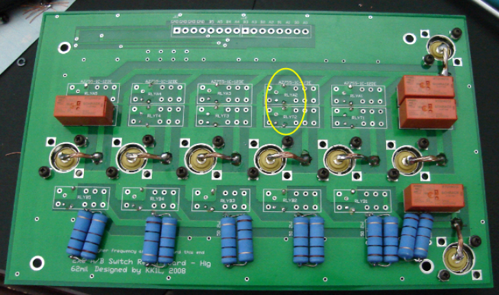 The completed board shown here. The paralleled resistors here are a set of 100 ohm 3W which I used to increase the power dissipation by about 5db. The board's wiring provides for 50 ohm termination of unused antennas but I was worried that poor isolation between the various antennas would deliver more than 2W into one of these resistors. With the 6W resistors, an isolation of 22 db minimum is needed and the models showed I would have that in all cases. In the typical use where isolation levels are normally higher, this measure would not be required. 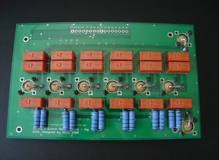
The mounting for the switch is TBD. But for evaluation, the SO239 need to be reinforced so that the forces of connected cables would not rest on the PCB. Some scrap aluminum strips and a bit of drill work provided the rough solution. 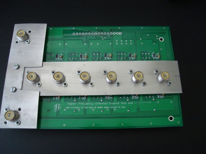
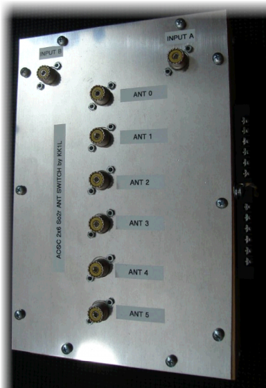
Final Construction Details Wood construction was legitimized by Richard Measures and I took a page from his book here with the antenna switch. For the final enclosure, the "T" scraps were replaced with an 8x12" 0.063" thick aluminum facing plate. This is mounted on a wooden structure tripple-layer lined with aluminum foil. The foil is clamped in place between the aluminum facing plate and the wood. The final structure is very strong. 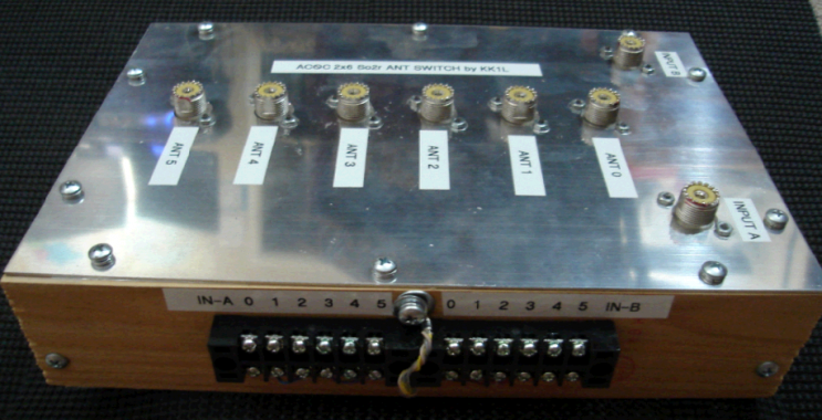
Control wires are routed via 3-turns through a big type-31 ferrite and then through the wood sidewall and onto the external terminal blocks. Not shown here, the backing is a single-sided PCB which covers the entire bottom. The result looks to be an inexpensive, RF-tight enclosure; ready for attic mounting. 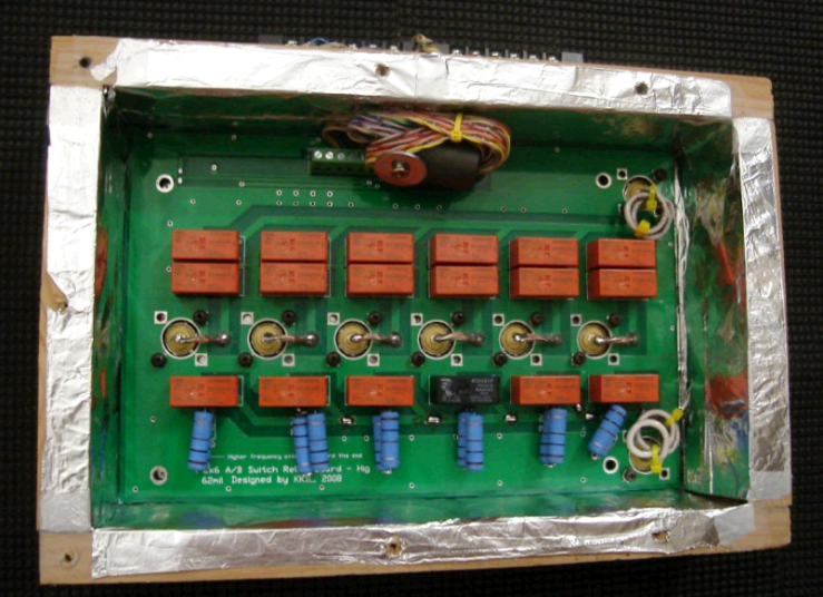
The finishing touch is provided by Brother labels. Isolation Measurements - No Antenna Selected Case Test: Input A to Input B Isolation Conditions: No antenna selected. Results: About 74 db @ 28 MHz; 68 db @ 50 MHz 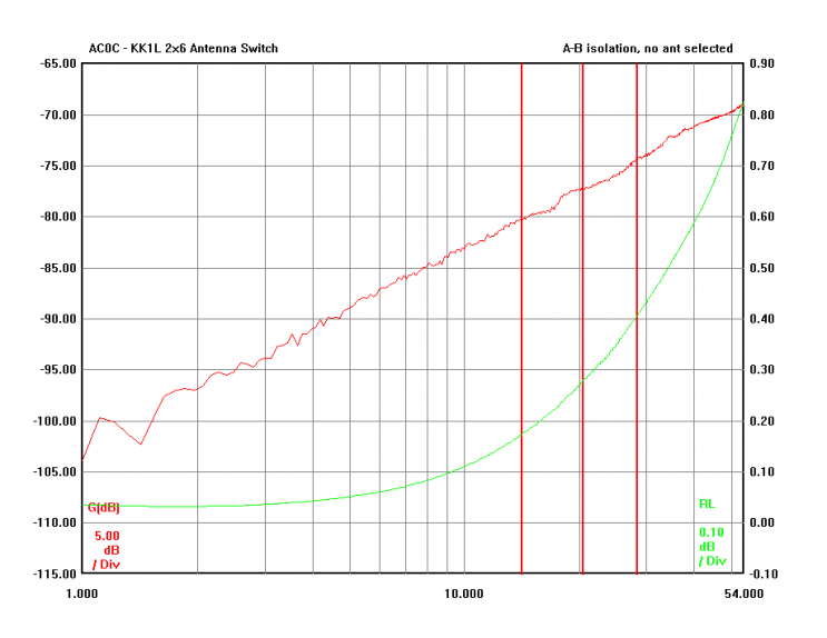
Test: Antenna Port to Antenna Port isolation trend vs. spacing Conditions: No antenna selected Results: A. About 50 db @ 28 MHz between any two adjacent ports (one SO239 distant) - e.g. port 0 & port 1 B. About 60 db @ 28 MHz between any ports spaced 2 SO239 distant (e.g. port 0 & port 2) C. About 67 db @ 28 MHz between any ports spaced 3 SO239 distant (e.g. port 0 & port 3) D. About 69 db @ 28 MHz between ports spaced 4 or 5 SO239 distant (e.g. 0&4 or 0&5) 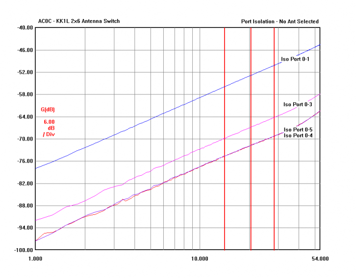
This data suggest that putting the worse coupling combination at least 3 ports distant would provide some benefit, although it needs to be weighted with the impact of SWR vs. position vs. frequency (see below). Isolation Measurements - Antenna Selected Case Single antenna connected to a single input. Unused input port terminated. Test: Unused port coupling to Input Conditions: Port 1 and Port 5 isolation with Antenna Port 0 selected by Input A or Input B - unused port terminated Results: 72 db or more on the A-input; and about 40 db or more with the B-input 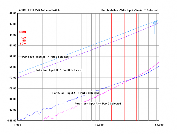
Test: Unused port coupling to Input Conditions: Port 0 and Port 4 isolation with Antenna Port 5 selected by Input A or Input B - unused port terminated Results: 68 db or more on the A-input; and about 40 db or more with the B-input 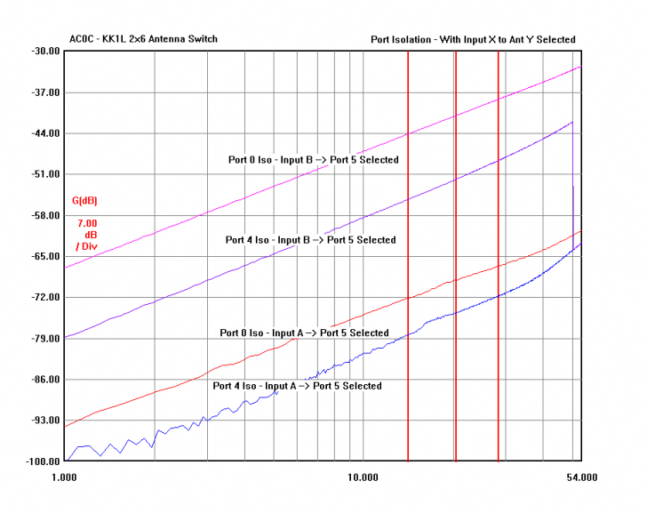
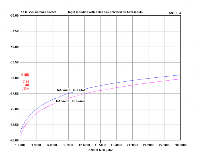
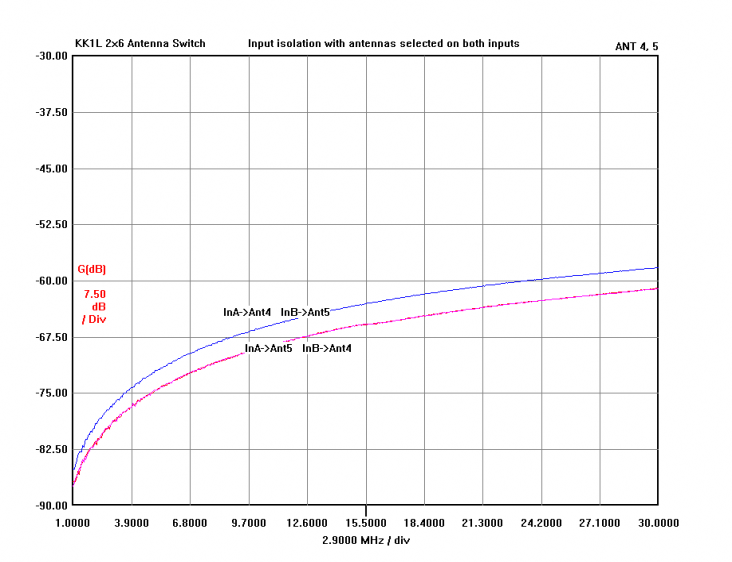
The difference in the Input A's superior performance over Input B is due to a double set of relay contacts when the A-input is used. The B-input has only the single set and the capacitive coupling of the open relays while small (about 3 pf per relay) does accumulate and provide a significant leakage path by comparison. The data tell me that, for my application, the best overall performance will be to feed the port B input into my other antenna switch because that provides the best isolation in the worst case 20m/15m coupling configuration. For other readers, this also means that you can expect to need a bit more coax stub or BPF work on the B-input rig side compared to the A-input rig side. Isolation Measurements - Both Antennas Selected This test measures the leakage between two selected antennas. This reflects the "normal" use of the switch. And here we see quite excellent isolation all the way up through 10m. 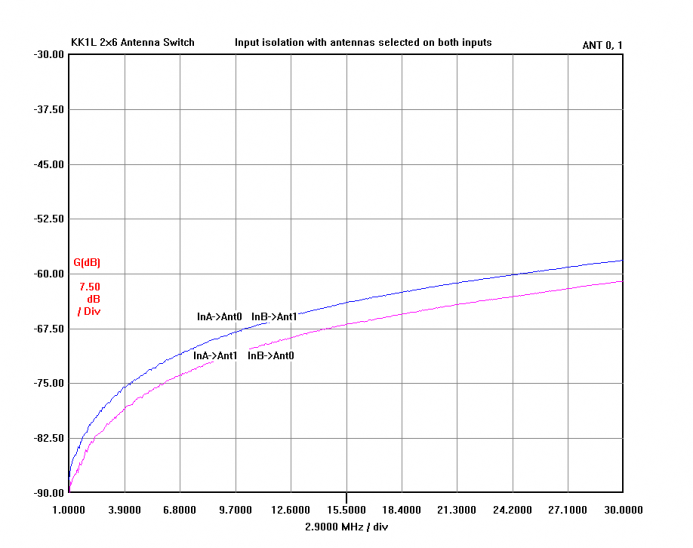
SWR Measurements SWR varies by port as the various reactances accumulate. KK1L specifies the higher frequency antennas are to be placed on the higher port numbers and that is confirmed in the sweep of the A0 and A5 ports here. In normal use, SWR of under 1.2:1 would be expected even if a dedicated mono-bander for 10, 15 and 20 were to occupy the last 3 ports. 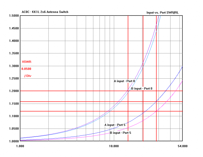
SWR Improvement? I wondered if it may be possible to improve the SWR a bit, The VNA suggested the load was overall negative reactance and so a series inductor may provide a bit of positive reactance to offset. To test the theory, after some trial and error, I finalized on a length of approximately 6" of #14 wire wound into a 3-turn coil. Then adjusted the spacing and positioning of the coil (which slightly altered the Xl) - to give the best overall SWR reading when feeding a 50 ohm termination mounted on the various antenna jacks. 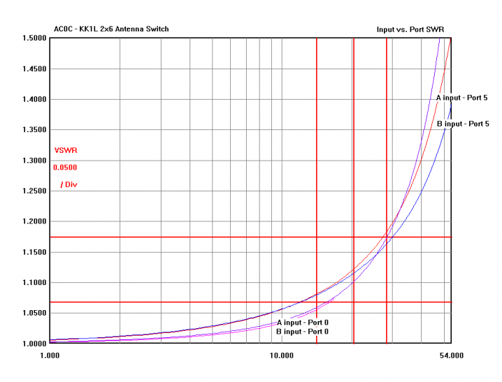
There is a trade-off here, in that the 6m performance will be compromised as the much higher Xl of the coil over-compensates. However, the performance of the antenna selections is somewhat more uniform over frequency, and is much less dependent on port selection. And I had no plans to run a 6m antenna from the switch anyway. Mod Results Before and after SWR readings into 50 ohm termination were as follows. Note especially the improvement in the A0 position. With the mod, the SWR is quite consistent in the 1.15-1.18 range for any input at 28 MHz. And somewhat less than this with lower frequency. Freq | OEM A0 | OEM A5 | MOD A0 | MOD A5 | 20m - 14 MHz | 1.20 | 1.06 | 1.07 | 1.07 | 10m - 28 MHz | 1.45 | 1.14 | 1.17 | 1.17 | 6m - 50 MHz | ~1.8 | 1.25 | ~1.6 | ~1.5 |
Finished board, with the SWR trim coils installed. I'm sure the coil construction could be done in a more elegant fashion but this method was quick, cheap and certainly effective! 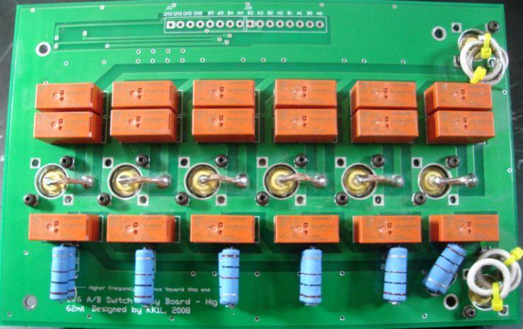
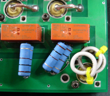 Port B coil shown here. Port B coil shown here.
|