Optimizing the 10m Antenna Hardware with The Long Awaited Arrival of Cycle 24 One of the big lessons learned in CQ RTTY DX contest in Sept 2011 was that the 10m is the new 20m. And that means a serious effort was needed on both the 10 and 15m attic beams. This page documents the work on the 10m beams. HistoryOriginally the 10m beam was implemented through a Mosley PRO-57 trapped DE. The DE would resonate on 10m, 15m and (originally) 20m. By adjusting the length of the elements outside the trap, the DE was converted from a 20m to a 17m. Thus proving 10, 15 and 17m service with the single element. For 10m service, a single fixed director was set on the east end of the attic making the 10m antenna essentially a 2-element beam, with fixed east orientation. At that time (2009-2010), with the sunspot cycle slow in coming, no further actual effort was made to improve the performance. After all, a dead band with a better antenna is still a dead band! All that has changed with the improvement in Cycle 24. And with the lesson of the CQ RTTY DX contest fresh in my mind, the challenge was to work up a new, improved design that would give the 10m band the attenuation it deserved. And hopefully, do the same for my high-band score in the next contest. Looking for a LocationThe 10m antenna as I had planned to build was going to be of a 3-element reversible type, similar to the 20m antenna. And given 10m elements are small, that provided a lot of flexibility on where the elements could be physically located. So the next step was to call on EZNEC to help me find a good location for the elements, at least from the model's perspective. To do this, I built a 3-element uniform spaced antenna in MMANA-gal and converted the dimensions into EZNEC. That design was tweaked a bit and served as the baseline of what an "ideal" antenna should look like in the model. I know from past experience that having all of these antennas located so close together, even decoupled in exotic ways, always causes pattern distortion, gain loss and F/B degradation. So having a "ideal" to work from let's me compare any proposed location within the attic space and judge what the impact is. That WAS the plan. The trouble turned out to be - there was not a single location for the 3-element beam that would give a functional and reasonably "clean" pattern compared to the stand-alone model. If the 3-elements were located near the east end, then the east-beaming pattern was good, but the west-beaming (which required going through all the wires in the array) looked very bad. I looked both at both the x-axis and z-axis moving the 3-element set through the entire space. Nothing looked promising. Then as this kind of thing often does, a solution came to me. Instead of building a single antenna which was reversible, why not build TWO antennas, each fixed on a given direction. So the east-beaming antenna would be located on the east end of the array, and the west-beaming antenna would be located on the west end of the array. Confirmation in EZNEC showed that this solution should be workable. The challenge was to consider what kind of beam should be built. 3-element vs. 2-element in the Attic ContextHistorically, I've preferred a 3-element type of reversible beam where the end elements are configured either as a director or reflector via a relay-switched inductor. For this design to work, the spacing between each of the 3 elements is uniform. Generally speaking, a 3-element beam of this fixed-spacing type does not offer much of an advantage over a 2-element beam from an outright gain or F/B performance perspective - however, it does have the advantage of being much more broad-banded and presenting a generally higher feed-point resistance compared to an equally configured 2-element beam. There are two challenges with a 3-element type design which comes into play though. First, the currents in the reflector are small compared to the director (perhaps 1/3). And with so many wires proximate to the 10m array, it's hard to ensure each of the other wires has low enough current levels so that they don't impact the beam's pattern. And generally for my attic beams, I want to keep the spacing close and the currents high so the coupling is tight - which ensures the parasitic action is occurring. Secondly, in reality, tuning the 3 elements is much more difficult than a 2-element type. Tuning the attic array is done by using the W8WWV RVM system - where actual current and relative phase measurements are compared to the model. For details on the RVM system, see Greg's Dayton 2008 Antenna Forum presentation found HERE. It's an iterative process to tune a given beam in this method. And typically, the measured currents are somewhat different than the modeled ones which is due to the other wires of the array (which are included in the model) and other things in the attic space (like the Rolex, AC conduit, water heater vent pipe, etc) which are not included in the model. Once the elements are close to the phase relationship targeted by the model, the actual phase/currents are pushed into the model as sources, and the pattern considered. This process continues until what is actually measured and then modeled looks as close to target as possible. Models - PART 1 So for the 10m beam set, I focused on the 2-element, close spaced solution. Minimum spacing was considered using MMANA-GAL and determined to be around 24 inches with as much as 34 inches being better if the physical space allowed. And because my mode interest is CW and RTTY, the antenna can be optimized for just the bottom 200 KHz of the 10m band . Even with this close spacing, the characteristics of the beam don't vary too much. After some design work was completed, final modeled placement of the 3 beams combining model and physical constraints looks like this below. One DE/director pair on the east end of the array (red color), another on the west end (also red color). 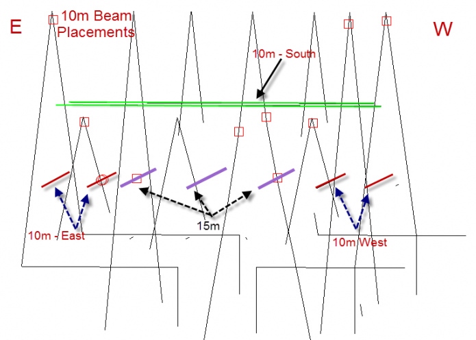
For reference, the modeled performance of a 2-element beam outside of the array (free standing) looks like this. 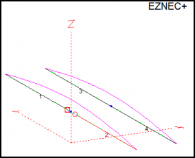
The stand alone model for the 2-element, based on a 30 inch spacing and about 154 degree phase shift. Reference model, AZ and ELEV plots here: 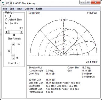
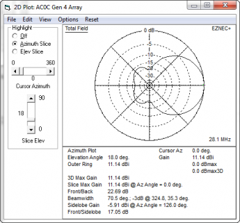
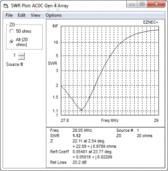
The model has tight coupling - running about 153 degrees of phase shift between director and driven element. And in the SWR plot, the effect is seen in a lowered feed-point resistance. Around 20-25 ohms at resonance. The modeled performance of the East beam inside the full model (with all other elements included) is: 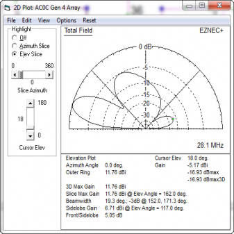 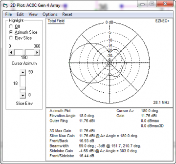
And the modeled performance of the West beam (with all other elements included) is: 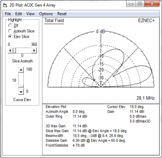
At this point, I had a nice looking design idea, that with the elements inside the full model, looked like it should work. Adding a South Beaming OptionOne of the problems with the array is that QTH located at 90 degree off the beam are in the null. And I know from experience that, while F/B may not be great on some of my antennas, the side lobes are very serious and very real. In the 40m phased drive modification, I worked around this by using a in-phase drive option which provided an omnidirectional pattern. It can be addressed, but it's not that easy... However, in this case, with the 10m elements being so short, I considered adding a 3rd beam option pointing south (green colors in the drawing above). That 2-element array would run the length of the array and is possible because the array has no physical boom as an outdoor antenna would have. Adding a "north" beaming option could be facilitated by configuring the 10m south (green) beam as a direction- switched array as many of the other beams in the array are now. Something to check into later perhaps... The 15m beam optimization will need to be done first though as it's a higher priority assuming the 3-direction plan works in reality as the models suggest.. The pattern was not wonderful, but it was better than nothing. And in the back of my mind, I was considering how to make this antenna point North (toward JA) as well as South (toward SA).... Enough with the design, let's build some antennas and (thanks to RVM) we can measure how they really look! The BuildThe beams are simply a pair of dipoles and with their attic placement, no special construction was needed. The more complicated "features" of the elements are related to enabling ease of tuning and the RVM system. BUILD: W8WWV RVM System Components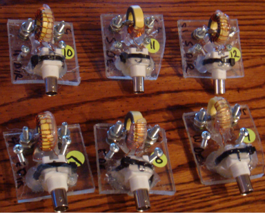
The RVM sensors were built on small scraps of 1/4" PS sheet. These are mounted on the wooden wire support and with their modular nature, allow for ease of removal, repair and calibration. Sensors are built from a T94-6 powdered core with 15 turns of 24 GA enameled wire. Prior sensors were built using type 43 cores which, at 10m, would have added a large series inductance with their presence. Heating was a factor as well and the large powered core should provide much better dissipation as well as much less of a lumped inductive component. 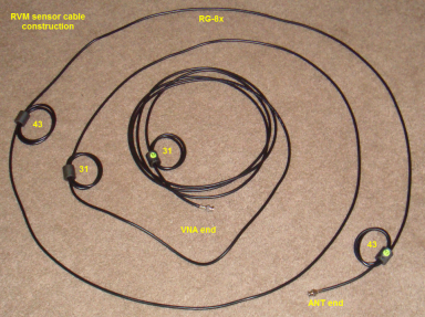
The RVM sensor cables need to be decoupled. In this case, I used 4 1.25" ferrites - with 3 turns per used. A type 31 is placed on one end and in the middle. And about 3/4 along the run toward the RVM sensor end and at the end are type 43 ferrites. The performance of the 43 and 31 on 10m is about the same. I used the 43 on the antenna end because I had the 43's in the junkbox and wanted to clear them out. 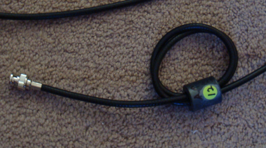
The RVM sensor cables are RG-8x with clamp-on BNC terminations as seen here. Labels on each end help keep the cables straight when testing. BUILD: Dipole Center Insulators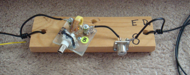
Dry wood is a FB insulator and that's what I used for this build. The board provides a good mounting place for the sensor, the SO239, strain reliefs, a mounting hole - and later, terminals for the hairpin match. Shown here is a completed DE board, ready for use. 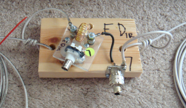
At right is the smaller board for the directors. The SO239 and shorting PL259 shown allow for easy connection of a MFJ259 for initial tuning purposes. The board is smaller because no provision for hairpin is needed on the director elements BUILD: Feed-line and Coax Chokes 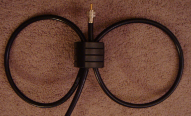
Feed-line is RG213 Coax chokes are built K9YC-style with 4x type 31 2.4" ferrites used per DE with 3 turns Another toroid is used on the coil of coax near the switch to provide a bit of far-end suppression of currents the cable may pick up. My thinking is... In an array like this, with so many wires in such close proximity, and so many bands, the assumption is that wires (including feed-lines) will act as unplanned parasitic partners unless ferrites are there to break up the action. BUILD: Final Kit - A Beam in a Bag! 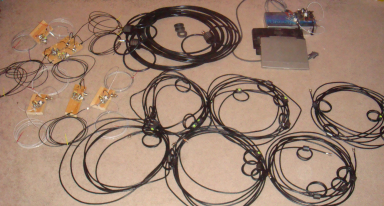
The final kit for all 3 sets of 10m beams is shown here. It composes: 6 dipole assembles, RVM sensors and cables, coax feed-line with chokes mounted and the RVM mux board and VNA with laptop. 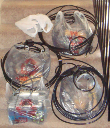
And here the beam kits are bagged and ready for transport to the attic. Would you like fries with that set of beams, sir? Initial Build ResultsThe east-beaming pair worked out beautifully. Interactions with the adjacent 15m director were less than the model predicted which (in this case) was a benefit. Very encouraging. The east-beaming DE looks like this: 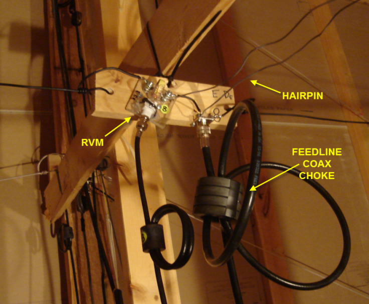
Unfortunately, Mr. Murphy made his appearance on the west beaming pair... I had made a mistake in the implementation - which was revealed when the resonant point of the west element DE (no director yet) was checked and found to be less than 20 ohms vs. a modeled 65 ohms or so. Uggg. The west wall stucco effect had come back to ruin my day. Read more about the stucco wall interaction problems HERE. Essentially, as the frequency is higher, the coupling effect associated with the stucco is much greater. In moving the DE away from the stucco wall, the effect is lessened but it turns out that about 6 feet of separation is needed to avoid working with single-digit resistance values! Unfortunately, that means a modification of the layout. And that means back to the model as a first step... Models - PART 2 Back on the drawing board... After a week or so of part-time model massaging, the final version of the 10m placement is shown below. Given the need to space the 10m away from the wall, and with a look to the future revision of the 15m antenna, and a re-trim of the 20m antenna, I converted the 15m and 20m antennas into 2-element reversible types. This is similar to the 3-element type except that what would normally be the reflector is simply broken by relay in the center leaving the single DE and director. And to accomplish this, some adjustment of the 10m east director into the inverted-v shape was needed. The 10m east and west beam pairs are shown in RED color below. Modifications to the 15m and 20m beams will be documented separately. Also, with further attention given to what would have been the south-beaming 10m array, it was converted to a single dipole element (green color) due to physical space constraints - adding the 2nd wire would have obscured the space available for movement and made future rafter climbing very difficult. 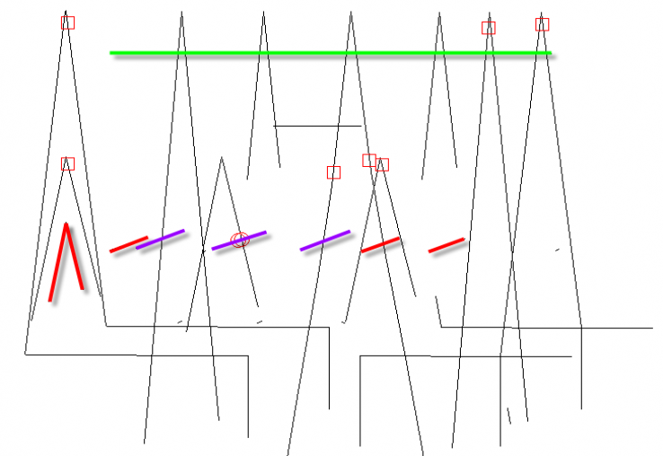
East and West beaming patterns are similar to what was predicted in the earlier model. The dipole model was not included and the modeled plots are shown next... DIPOLE Model PlotsThe following plots are for the dipole element, and are based on the model only (there is no relative phase to measure in a single element configuration). However, if the model is correct, then the radiation pattern of the apex-located dipole should look like this: 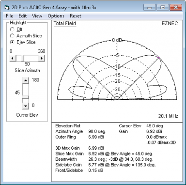
N-S DIPOLE elevation plot Notice the two lobes here, the first at 12 degrees and again at 45 degrees 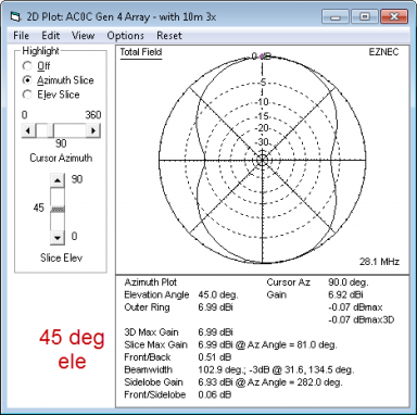
N-S DIPOLE azimuth plot - 45 degree For the short skip... 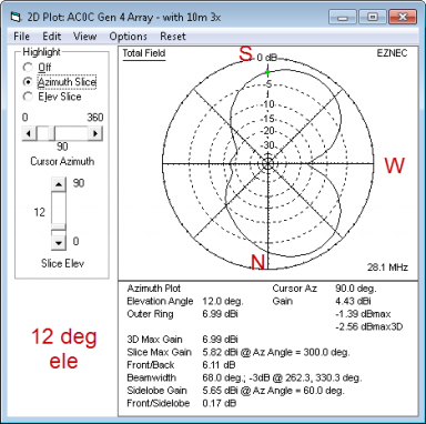
N-S DIPOLE azimuth plot - 12 degree For DX RVM Results from the Final Build 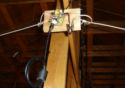
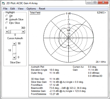
With the new location, the west beaming pair results were much better. The director assembly is shown in the photo (right). Tuning still proved to be quite difficult but a final solution was found that looks good. Final feed-point resistance was about 12 ohms resistive and hairpin adjustment was critical. Measured current/phase values across the band of interest for the two beam pairs are as follows: East ============== 28.0 1.28 -151 28.1 1.20 -155 28.2 1.13 -158 West ============= 28.0 1.47 -159 28.1 1.18 -165 28.2 0.99 -169 And placing the 28.1 MHz currents into the combined model as current sources, provides these modeled plots below. Note that these plots show predicted radiation pattern based on the actual measured currents present in the antenna as built - and to the extent the model represents the environment, it should be "real." This of course does not include the non-modeled items like the stucco wall, or any of the things physically surrounding the antenna (roof, AC venting, Romex, etc). But it is likely the most accurate estimate of the actual antenna performance possible under these circumstances. 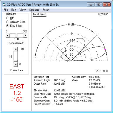
EAST BEAMING elevation plot The EL and AZ for the east beam looks very nice and clean. 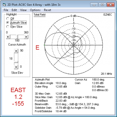 EAST BEAMING azimuth plot EAST BEAMING azimuth plot

WEST BEAMING elevation plot 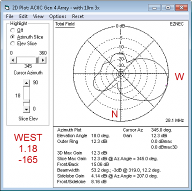 WEST BEAMING azimuth plot WEST BEAMING azimuth plot
The lobe location (off line) is due to a small difference int he modeled dipole lengths. It's actually in-line. Final Construction Details The west beam wire pair is shown below: 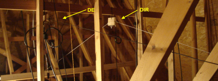
Here the N-S dipole can be seen running the length of the attic "boom." The coax coils left of the dipole are components of the 160/80/12m dipole. 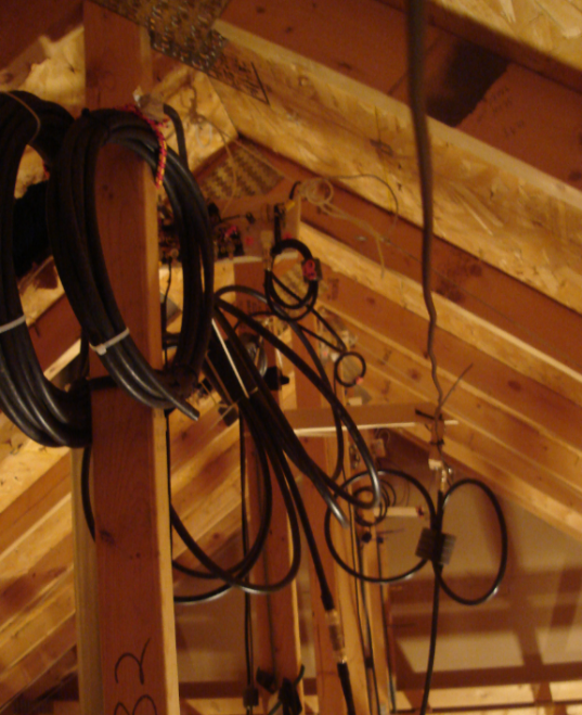
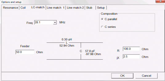
After trimming for resonance, the 10m dipole had a pretty high resistive feed point value. The model predicted this as well and it's due to the proximity of so many other wires. The solution was a simple L/C lumped match. I measured the Rs/Xs with the VNA and then used the L/C match tool in MMANA-GAL to find values. 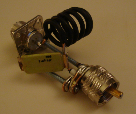
I had some surplus 60 pf transmitting caps and used one of those. The coil is wound from 14 ga antenna wire. A bit of hardware made it self-supporting. After mounting a small antenna length adjustment provided a 1.2:1 SWR - down from the 2.4+:1 without the match. In the shack, thanks to some RG-213 cable loss, the SWR is 1.05:1 or so across the CW/RTTY part of the band. Compared to the 2-element brothers, this kind of wide-band performance is really nice to see! 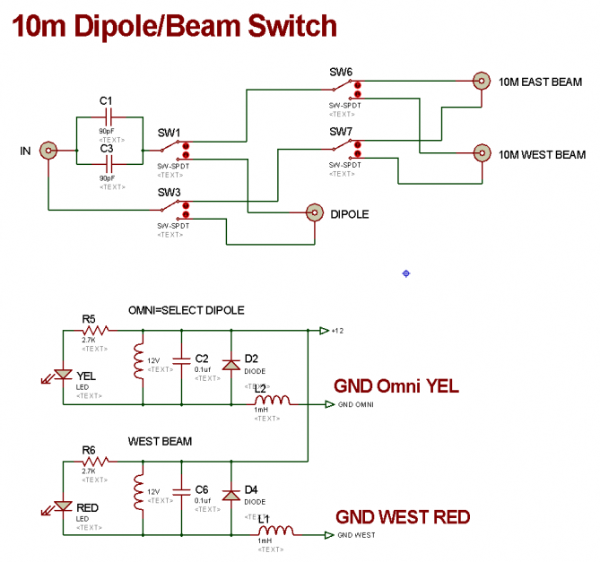
The small green squares are caps used to counter the inductance of the relays and interconnects. The two caps are slightly higher in value than ideal but produce acceptable SWR matches into a 50 ohm cal load of 1.06:1 (E), 1.12:1 (W) and 1.25:1 (D). 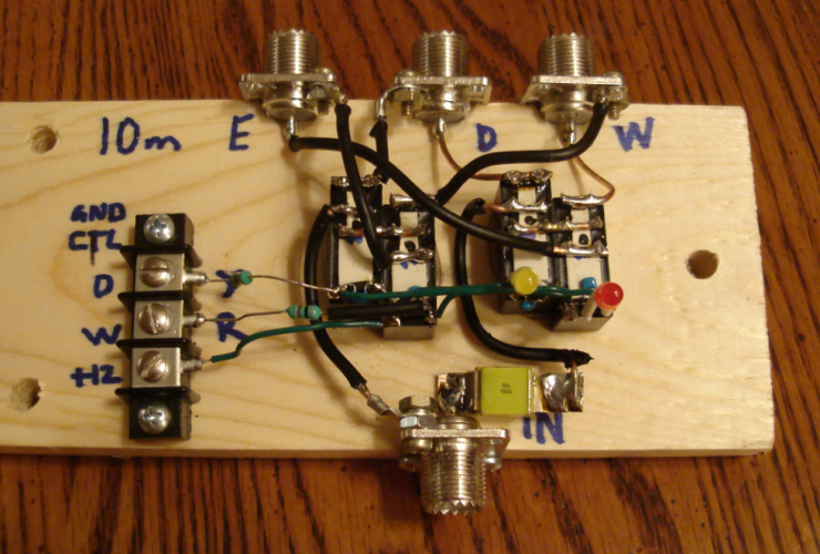
Below, the 10m antenna switch mounted in the attic. A common mode choke is fitted between the switch input and the coax 15/20m stub filters. 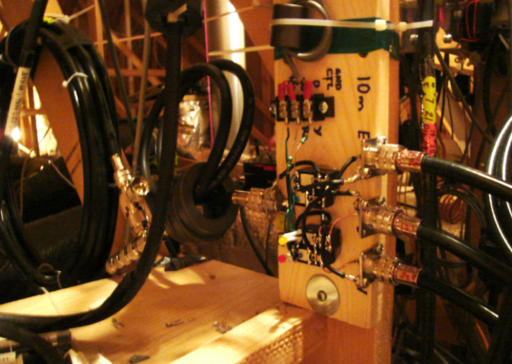
ConclusionThis turned out to be quite a big project in retrospect. Had the stucco underlayment mesh not been present I'm sure that the first build model would have worked as modeled but that's the nature of this kind of project. In any event, the antenna responds properly - signals physically located from a given direction are stronger on the associated antenna. And the F/B of the east and west beams is good. There are a few 10m contests and a bit of time spent there will provide a first-class test of this new antenna trio. IF we can get some decent sunspot activity!!! |