Encouraged with the results of the 10m array rebuild, next up on the overhaul list is the 15m beam. Design ChangesFundamental changes were to move the DE and west end director element a bit further away from the west end stucco wall. And to convert the prior 3-element (directory-DE-reflector) design into a 2-element (director-DE) type. The 3-to-2 element design further minimizes any performance impact from the parasitic effects that the west-side element will necessarily feel because of it's closer proximity to the stucco wall. The new 15m beam position (red color elements), and it's adjacent 10m elements (green color) are shown in the drawing here: 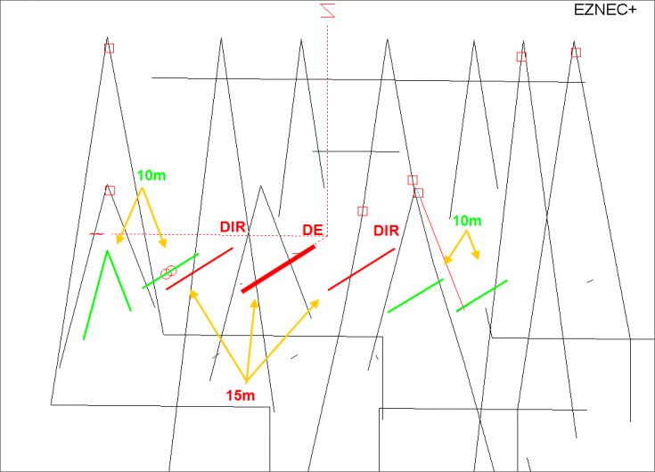
Adding Stubs into the Relay MixOne design refinement with an So2r application is to consider the various interactions of the adjacent operating bands. And to simplify things, I assumed that operation would be on adjacent band pairs. So 10m-15m and 15m-20m were expected operation pairs, but (for example) 10m-20m would not be - with the thinking that I would want to run the two highest bands that were operational. The prior design used relay switching to determine element operation "state" - director or reflector for the 3-element designs and directory or open in the 2-element design. This works very well in the So2v or So1r single rig use. However, with the higher bands 20-15-10, there is some interaction between elements on adjacent bands. The interaction can be tuned around if the element is static, but for So2r it's not as easy. For example, on 15m, there is some interaction with the 20m beam elements. The 20m beam elements will be configured as "closed" when operating as a director - or "open" when the beam points the other direction. The adjacent 15m element will couple differently with this 20m beam element in different ways depending on the open/closed value. And the change in coupling will cause the 15m antenna phase relationship to move around. The same situation impacts the 10m beam as the 15m antenna direction changes. An example of the fixed 10m east beam changes - as the adjacent 15m east element is opened and closed - is shown below. In this example, the elevation plot and F/B sees minimal change. However as can be seen from the red note comments, there is a roughly 18 degree phase shift change. That phase change will result in SWR changes as well. In most of the other close-spaced beams (including the 15m 2-element design), a phase shift of 18 degrees will result in a more significant change in F/B. 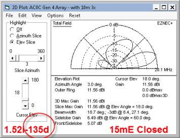 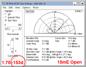
Fortunately, the model suggests an interesting solution. First, the 10m beam is not a switched variety - it's static - only the 15 and 20m beams element configurations will change. And secondly, the interaction seems to be more significant to the next -higher-band. That is, the 20m elements impact the 15m antenna more than the 15m element open/close status impacts the 20m antenna. And lastly, the beam performance is largely the same, after retuning, if the adjacent lower beam's elements are EITHER open or closed, with the closed case being a bit better. So the challenge is how to make the element appear the same to the higher band , while preserving the open/close function. My solution to this was to use a half-wave open stub in parallel with the relay. The stub is tuned so that it's an electrical open at the lower band (e.g. 20m), and serves as a near short at the higher band (e.g. 15m). A half-wave open segment was picked because it's higher Q provides a lower Z "short" than a quarter-wave shorted one. An example of the stubs present on the 15m antenna is shown in this Elsie plot below. Notice the stub will provide a low Z value pass through to 20m and 10m, and it will provide a high Z value on 15m. On 15m, the open/short action is provided by a relay in parallel with the stub. The net result of this is that the 15m element has a closed and open behavior to 15m signals, and that element, from a 20m and 10m perspective, looks electrically static. The design objective is that the 20m and 10m element will see minimal phase change as the 15m is operated in it's open or short configuration. 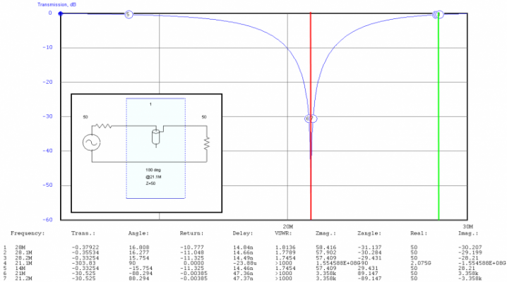
The control structure which facilitates the directional control is present on each director and has this circuit: Notice the inclusion of an extra SO239 for easy connection of the MFJ-259 for preliminary tuning. And the RVM sensor tap for phase magnitude/angle monitoring for use in fine-tuning the antenna - and verifying the operation of the stub/relay decoupling action on the up-next-for-modification 20m beam. 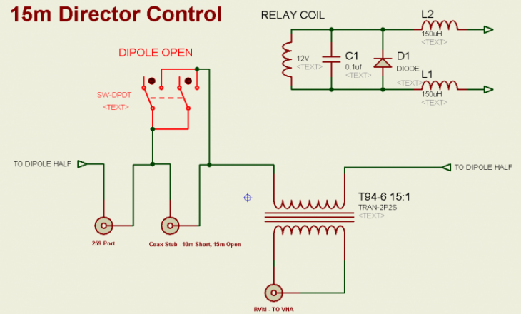
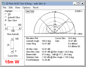
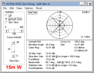
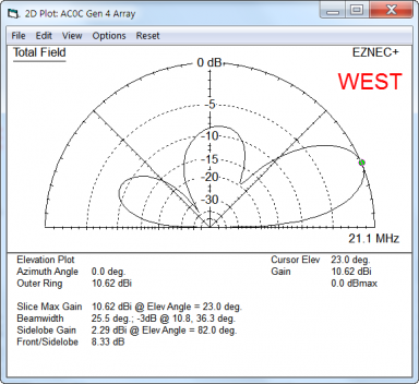
. ModelsEZNEC+ predicts the following characteristics for the azimuth and elevation. First beaming east, then beaming west. Compared to an "ideal" antenna (meaning a 2-element at the same height, over same ground), the gain looks good and F/B is acceptable. As with the 10m beam, it's hard to get a "clean" backside rejection with all the other wire around. 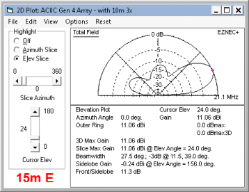 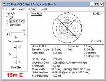
Other configuration settings call for the following. And are adjusted via a line in the firmware code for the main controller: - 10m enabled - don't care
- 20m elements - don't care
- 30m elements - closed in center
- 40m elements - open in center
- 80m dipole - open in center
- 80m dipole iso relay - closed
RVM tuning target - about 155-160 degrees. Estimated feed point resistance - 12-15 ohms resistive at 21.1 MHz east, and about 20 ohms resistive at 21.0 MHz for west. Build Details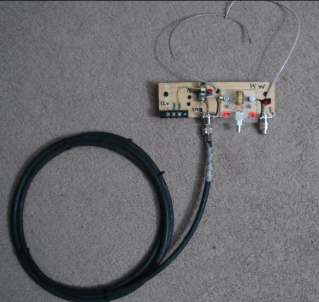
The construction is simple with everything mounted to a wooden backing board. It's configured to hang below the current aluminum tube elements. The 6m and this 15m beam are the only two beams built from aluminum tubing - the rest are of a pure wire variety. The gray 12 Ga stranded THHN wire extending above the board will be trimmed, terminated and connected to the center of the dipole elements. Unusual for this project is the coax stub, shown here below and left of the board, coiled. It will be suspended beneath the SO-239 as shown in the picture and, assuming the stub works as planned, it will be secured to a stud so the SO-239/PL259 joint does not need to provide the mechanical support as well as the electrical connection. On the right end, the SO-239 with a shorting stub provides a quick connection point for an MFJ-259 or similar. This is very handy when an element is first put up. I measure roughly what the element length is, and then trim it in from there using the MFJ. The connector provides enough strength so that the MFJ can "hang" from the connector while the trim is occurring. In the center, the RVM sensor is removable for calibration, if needed. And on the left side, we can see the relay which serves a shorting function across the stub. The tuning of the stub was something of great debate while working up this solution. It's been trimmed in the normal method with the VNA - to have a peak Z at 21.1 MHz. However that frequency accuracy may not be the actual resonant point when used in this application as it's arguable that the wire length running to the SO-239 is additive. I had kicked around an idea of trimming the stub in place, and using the VNA to run a signal across the entire block structure, end to end, and I think that would work. However, the simulation looks OK in Elsie and I'm pretty sure it will work as intended. My thinking is that the normal VNA trim method does add a bit of space via the T connector (which is not present here) and that would offset the leader space roughly. And the trim actually does not need to be precise. To avoid affecting the pattern significantly, the current only needs to be reduced to a level of about 10-20% of that when the relay is shorted - and the stub can be off tune by quite a lot while still meeting this requirement. And just in case the stub solution does not work for some reason which will be obvious once tested, the wooden block has a lot of space on the left end to allow for later rework - if needed. The 3rd terminal on the connector (now unused) is present for the same reason. If the stub does work, then I will instead call this space and terminal provision "thinking ahead to accommodate future ideas..." :) 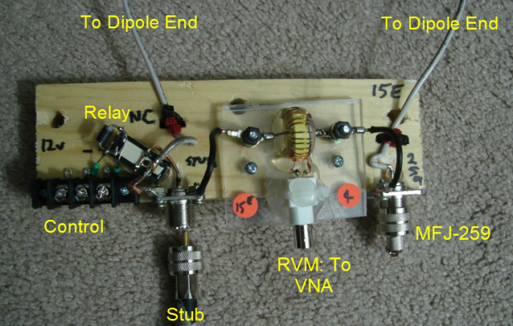
The control assembly mounted, shown below... 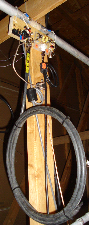 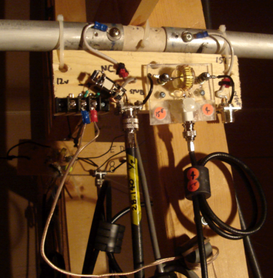
ResultsMeasured current magnitude and phase from the RVM, and used as sources in the model, provide the following elevation plots. East West ---------------- --------------------- 21000 1.55 -152 deg 1.38 -153 21100 1.49 -157 1.34 -156 21200 1.42 -161 1.31 -159 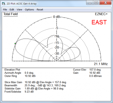
|