
Over the last few months, a few hams have sent me messages asking about the Inrad comment that their filter did not make a meaningful improvement in the rig's performance - and wanting to get a better explanation as to why the NS filter test results are so much better. Many felt that Inrad was saying improvement was not possible with a filter change - and that was confusing to a few hams I had discussed the topic with. Fortunately, Charlie W5VIN had one of these filters sitting on his bench, unused now after being displaced by the NS filter - and was kind enough to loan it to me for characterization. Charlie had featured the Inrad 912 in prior work with the 2K as part of the famous "Charlie Mods." And having the filter here on the bench provided an opportunity to get some actual bench data on the filter and allow me the chance to look into this question a bit further. The OfferingThe filter in question is Inrad catalog number 912 found here:http://www.inrad.net/product.php?productid=236 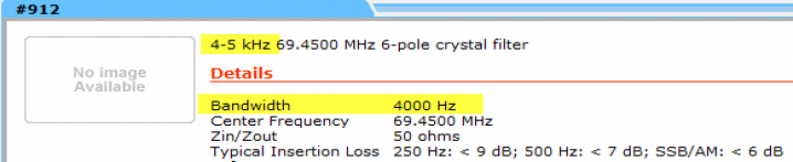
The bandwidth of the filter characteristics are unclear - listed as a "4-5 kHz" filter on the top line, and under the bandwidth section, "4000 hz." No transmission plot is provided for the filter. 50 ohms nominal termination with the correct center frequency for the FT-2000. Insertion loss is not given specifically, but rather generally in the table where I interpret it to be as "<6db" typical The Statement The confusion stems from this statement found on the announcements portion of the Inrad web site linked here: http://www.inrad.net/inrad.php?mode=announce , and which says: 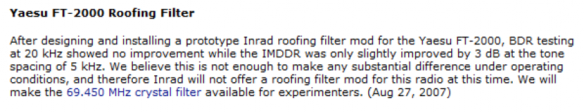
No details are offered as to the installation method, termination used or test setup. And when I spoke with Inrad in 2009, this position was reiterated again then. Bench Results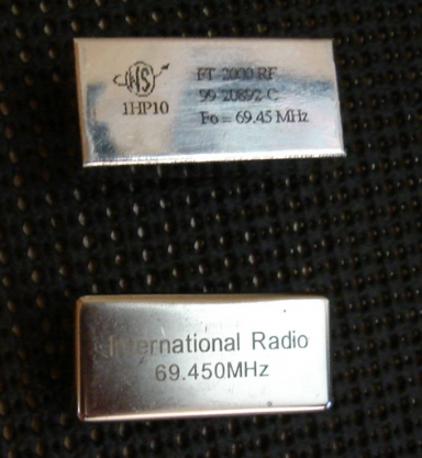
Shown at right are the NS filter and the Inrad filter. Test data was taken from an N2PK VNA using standard 50 ohm terminations and a fresh cal. In this first VNA plot (below), we can see a comparison of the 4 filters of interest. Yaesu FT-2000 original 6 KHz filter RED Yaesu FT-2000 original 3 KHz filter BLUE Inrad #912 PURPLE NS Roofing filter PINK Insertion Loss The Inrad filter has an insertion loss of around 5.5 db meeting it's advertised specification of "<6 db." Insertion loss is not of interest with respect to the DR3 performance, and to allow for easy comparison, the loss of the Inrad filter is increased by about 5db in this graph so that it's in line with the IL of the other filters. Bandwidth and Center Frequency Tuning The bandwidth of the Inrad filter is similar in size to the Yaesu stock filters, although it's much more properly centered. Note the two Yaesu filters are shifted to the left quite significantly. Focusing on the transition band (the slope of the filter from the top to the bottom of the graph), we can see the right side is quite similar to the stock Yaesu, and somewhat tighter than the Yaesu on the left side. The NS and Inrad filter skirts are steeper - a reflection of their 6-pole construction vs. the Yaesu MCF which are 4-pole types. 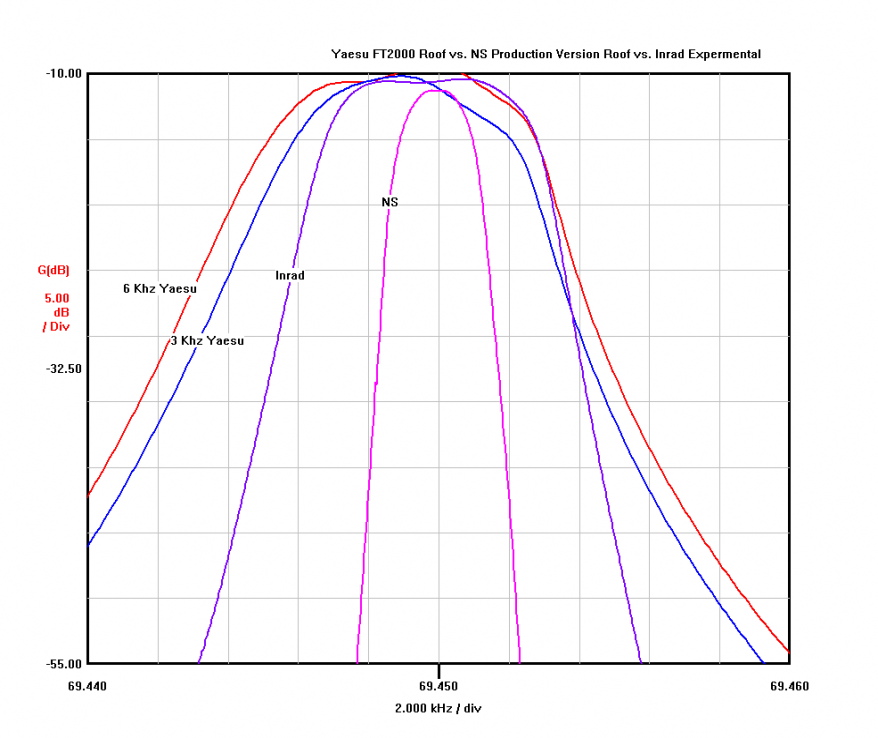
In this graph below, we have removed the Yaesu filters to allow for a more direct comparison of the NS filter to the Inrad. The -6db points of the two filters are: Inrad: 6350 hz (BLUE TRACE) NS: 2375 hz (RED TRACE) In this test, it's not possible to verify the "4000 hz" or the "4-5 kHz" bandwidth claims. The filter is much more a 6.4 KHz filter than it is something less. Reversing the orientation provided a similar response. By comparison the Yaesu FT2000 stock 3 KHz filter is around 7 KHz wide which is why the passbands of the filters matched so closely in the last graph. We can see in this plot that the Inrad filter is shifted very slightly below the optimal center frequency by perhaps a few hundred hertz. The effect of the filter being off center is a slightly different tonal distribution when comparing USB to LSB. And the DR3 will report better in one measurement vs the other (tones above or tones below). Again, in comparison to the Yaesu stock filters, the amount of error here from idea is small in comparison. 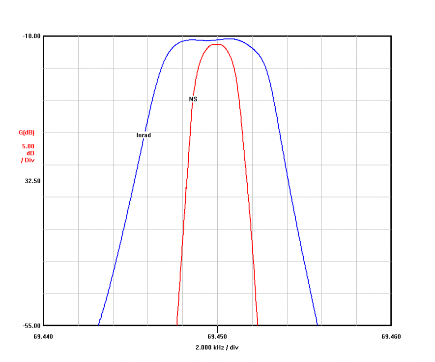
IMDDR3 Testing Comments Both Daniel and Charlie have prior published works that have reported varying levels of improvement using the Inrad filter both alone and in combination with splitter termination and other complicated mods. Generally these mods provided better performance improvement than the Inrad claim of "about 3db." In an analysis of the filter response, we can see take a good look at where the benefits they observed come in. And see how the NS filter looks in comparison. For the VNA plot analysis below, the red vertical marks represent the location of the primary test tones. The green vertical marks represent the location of the third-order IMD products which are created within the first mixer. A DR3 test can be thought as simply the difference in the levels of these two tones within the rig (the IMD product vs. the primary test tone). The benefit any roofing filter provides is in it's ability to provide attenuation of these adjacent signals. And by suppressing the level of these unwanted signals, the downstream mixer, amps and other parts of the receiver strip have only our primary signal of interest to contend with. So both the levels of the IMD products generated at the first mixer, as well as overload by-products of the follow-on stages is minimized. Each vertical division in the graph is 5db. We can see that the attenuation of the nearest tone by the Inrad filter to be 1-2db on the right side, and almost zero benefit on the left (an effect of the wide passband and off-center filter tuning). By comparison, the NS filter is providing about 33 db of attenuation at the similar point. The attenuation seen here does not translate directly into the a 1:1 benefit in DR3, however, we can conclude from these graphs alone that the improvement in the rig's performance due to the Inrad filter shape is expected to be very minimal when using the Inrad filter. And by the same examination, we can expect - and in fact do see - a huge improvement with the use of the far more selective NS filter. 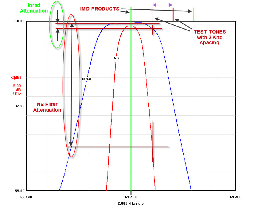
With the minimal anticipated benefit of the Inrad filter due to the attenuation of the other signals, there are benefits in using that filter over the stock filter as Daniel and Charlie found. Primarily in a steeper skirt vs. the Yaesu filters and with wider test tone spacings in the 5 KHz and wider range. With some additional work done to provide matching as Charlie and Daniel have with the splitter, the improvement in DR3 is more significant simply because the passive IMD created by the Inrad filter is less than the Yaesu filter. Conclusions The pros and cons of the Inrad filter, in comparison to the Yaesu FT-2000 3 KHz stock filter, may be summarized in this way: PROS (vs. FT2000 Yaesu 3 KHz filter) | CONS (vs. FT2000 Yaesu 3 KHz filter) | Lower insertion loss | Almost the same bandwidth as the 3 KHz Yaesu | Better shape factor (6 pole vs. 4 pole) | Insignificant improvement in standardized 2 KHz DR3 testing | Smoother passband | Significant cost | Incrementally better rig performance | Significant (undocumented) installation required |
From this work, we can objectively conclude that Inrad statement was accurate regarding the performance limitations of the Inrad 912 filter. Inrad, to paraphrase, is really saying that 1) given the filter's cost, 2) nearly same-as-OEM bandwidth, and 3) anticipating the difficulty of the installation, makes the product unmarketable as an improvement path for the FT-2000 owner wanting significant improvement in the rig's performance. The bandwidth numbers published are not verified in my test (6.4 KHz vs. 4-5 KHz advertised specification) - but the other filter attributes are confirmed. |