Step by Step - Installing the NS Roofing Filter into the FT-2000 For the FT-950 - CLICK HERE FRENCH language installation guide - and comments by Ludovic F5PBG - Click HERE Hams Providing NS Filter Install Services - CLICK HERE  Download this install page (3Mb PDF) - 6 June 2011 Download this install page (3Mb PDF) - 6 June 2011
IntroductionThe installation procedure that follows is well tested and will provide excellent results. The modification is simple in that the real challenge is primarily the exceptionally small board dimensions involved. Complexity is similar to the first Charlie W5VIN Mod. And much, much simpler than a Softrock, for example. This installation example is our suggested procedure - but it's not the only possible implementation method. Amateurs with RF design experience and a thorough understanding of the rig's operation may prefer to vary one detail or another. Likewise, individuals with high levels of SMT experience may prefer a differing material set (use SMT instead of leaded packages, for example) or a varied wire dress, etc. However, for the amateur operator who wishes to follow a known-working method of installation, the steps below should enable the full use of the filter's capabilities - without necessitating any design work or requiring test equipment for alignment. The explanation here is very detailed and may give you the impression the installation is complicated. It's not - we have added more detail than you may need because installers of all skill levels - from expert to novice - are following these instructions. CautionsThis example is for illustration purposes only. I cannot be liable for damage to a rig under any circumstances. While it's complete to the best of my knowledge, this page may contain errors, omissions, or use language that is not easily understood especially via translation software. Only proceed with this modification if you have the required skills to perform the work described below. That includes following proper EOS/ESD precautions and that you have adequate lighting, magnification and soldering implements suitable for the projects scale. Risks: The primary risk to your rig is that you accidentally create a short circuit across one of the signal paths. This does NOT typically damage to the rig. If you have experience working with SMT and a basic understanding of VHF techniques (meaning keep things short, neat, and tidy), it's easy to perform this installation. Because of the very small size of the features on the board, exceptional care must be taken when making the connections. The PCB is a multi-layer arrangement with a ground plane in VERY close proximity to almost every trace. Fortunately, the solder mask is of good quality and with care, inadvertent shorts are not as easy to create as one may fear. With the legal disclaimer out of the way... On with the detail! Tools NeededMagnification: The first of the 3 needed tools is magnification. If you have marginal magnification but good SMT skill, the operations can be accomplished. However, inspection will be difficult. In this case, it may be helpful to use a digital camera to take a photo of the area with good light and a high pixel count setting - then review the photo on the computer screen where you can zoom in for a better look. I used this approach many times on this and other projects. While it's not fast, it certainly is effective. Lighting: The second needed tool is good lighting. A 9-LED flashlight is excellent for this as you can move it around to avoid shadows. Soldering Iron: Use a hot iron and keep the dwell times as sort as possible. Read these instructions fully before starting. Compare the drawings with what's found in your rig. And double check your soldering points before making the connection. The rig should be completely disconnected from any other wires. The soldering iron must be grounded to the rig. And the operator equipped with an ESD strap connected to the rig as well. Yaesu cautions that lead free solder be used for all connections to the rig. See notes at end for more on this topic. Installation Summary of StepsThe installation replaces the existing 3 KHz Yaesu roofing filter with the AC0C NS roofing filter. Access to the main PCB where the filter is connected requires removal of the top and bottom black outer clam shell coverings (all these are black-colored screws). And removal of a shielding plate from the bottom of the rig (silver colored screws). TIP: Save the screws in a small container to avoid misplacing them The "expert version" of the installation steps are (full details follow later down the page...): 1) NS filter preparation A. Filter orientation B. Coax preparation C. Mount input matching parts D. Mount coax to filter
2) FT-2000 preparation A. Remove R1498 B. Cut trace to T1040
3) Final assembly of filter into rig A. Connect output side coax to PCB B. Connect input side coax to PCB C. Test D. Solder tak the filter in it's final location Note: VHF RF Practices ApplyThis filter operates at 70 MHz. Which means you will want to keep the unshielded part of the center coax short - as short as you can while still comfortably soldering the connections TIP: In the example below, the leads are longer than what would be ideal. Leads are shown longer in these photos to make it easy to see where the connection points are. Explanation: Exposed sections of the center coax do not seriously affect the IMDDR3 performance. However, the shorter the exposed center conductor is, the better the ultimate attenuation will be. And preserving the filter's ultimate attenuation performance . Short lead lengths is a preference - not an absolute requirement. Shorter is better - but don't make the lead so short that you risk creating a short in the signal path. Use the specific connection and grounding points shown only Service Manual Pages - for ReferenceReferences below are taken from the latest service manual published, TS-EH025H90D. Later versions may be available but the method is equally applicable. And while it's a great idea to have this document in your library, the drawings below are sufficient to perform the mod successfully. If you want to follow along in your own copy of the TS, the work will take place in this section of the schematic - highlighted here (blue highlight, right-top) - taken from page MAIN-9 in the D-TS version: 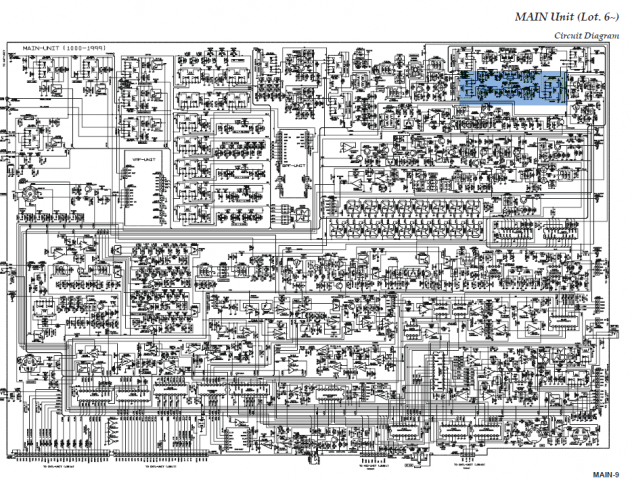 And the component drawings are from this region of the PCB drawing. Section E3 & E4 (blue highlight) - from page MAIN-11 (in the D-TS version). 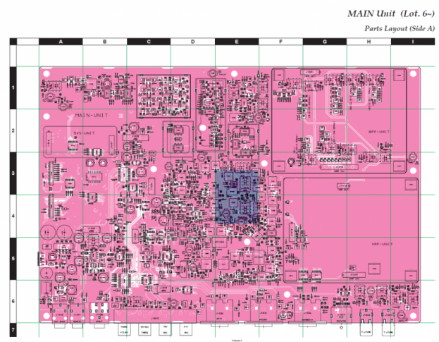 Finally, the area of interest for this install is found on the main circuit PCB. In this case, the front panel controls are located to the LEFT. Our work will be focused on the part of the PCB in the yellow square. Most rigs will have this red colored trimmer cap and that serves as a very useful "landmark" for helping to orient the pictures to follow. Some rigs may have additional strapping from the shield to the coax just right of the yellow box. In the pictures following, I have included the red trimmer in most to help with easy orientation. To gain access to this section of the rig, first remove the outer casing from rig (top half, bottom half) and then the protective bottom shield plate. 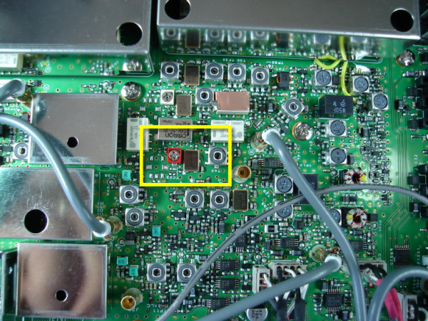
And now for the actual install procedure. Good luck! And you will be pleased to know that when complete, your rig will feature a world-class roofing filter capability previously unknown to any up-conversion rig on the market, at any price! FILTER INSTALL PART 1 - NS Filter Preparation Overview: The first part, "NS Filter Preparation" involves confirming the filter's orientation, fitting the input L/C parts and attaching the coax jumper to the L/C input network. FILTER PREP STEP A - FILTER ORIENTATION 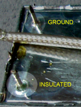
The filter has an orientation. To determine which end is the filter's input, reference the RED DOT marking. The end with the RED DOT symbol is the filter's input. [If the red dot is missing, then the input side is the end with the NS logo.] The filter has 4 pins on the back. Reference the photo at left. One of the pins on each end is the ground connection. The solder
tin connection to the pin and the case is visible. 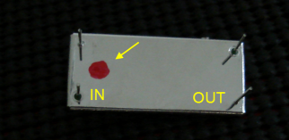
The insulated or "hot" connection is the pin with the small dark ring
surrounding the pin. If you are unsure, use an ohm-meter to double check. The "hot" connection
will measure with NO continuity indicated. FILTER PREP STEP B - COAX JUMPERS Cut two lengths of micro-coax about 70 mm (2.5") long. The exact length is not critical but this length is convenient as we will see in later pictures. 70 mm (2.5") is about the minimum length required for a convenient install. Strip about 10mm (1/3") of the insulation from each end and prepare the ends - bending roughly like the picture below.
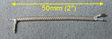
TIP: The center conductor will break if it's cut or nicked. FILTER PREP STEP C - FILTER INPUT MATCHING NET On the INPUT side of the filter (the pins adjacent the RED dot), connect the cap and inductor according to this schematic and orientating the parts similar to the photos. 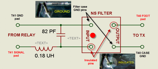
While the ground pin can be used, for best results, solder the shield directly to the case as shown below.
Suggested input matching network assembly:
- The capacitor is placed from the "hot" input pin - the other side is soldered directly to the case. Keep lead lengths short.
| - On the input side "hot" (insulated) pin, connect one lead of the inductor. At this point, the input pin will have the cap and inductor attached.
- Finally, one end of the coax jumper is attached to the other side of the inductor. Keep exposed coax leads and trim the inductor lead short.
- Solder the coax shield directly to the filter case.
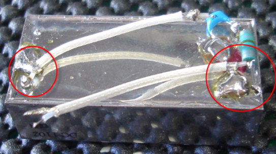
Make sure the coax center / inductor solder point does NOT contact the case or that will result in a signal short. TIP: A small bit of heat shrink tubing, hot glue or other insulation method may be used to improve cosmetics. At this point, the filter preparation phase is complete. FILTER INSTALL PART 2 - FT-2000 BOARD PREPARATION In this section, we make the adjustments to the main rig PCB to accept the filter connection. BOARD PREP STEP A - REMOVE R1498 Overview: Signals from the mixer are routed to either the 3KHz or 6 KHz filter by RL1024. So our first step is to break the connection from this relay to the existing 3 KHz filter by removing R1498. R1498 is a zero-ohm resistor and is part of an input matching network (all the yellow shaded schematic parts) that was not mounted on the final production version of the rig. TIP: The 3-stars *** marking on the schematic is Yaesu's notation that the part is NOT mounted on the PCB in manufacture. Remove R1498 - shown here on the PCB drawing and on the actual PCB (below). 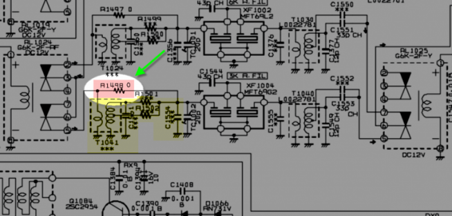
PCB view of the resistor we are going to remove... 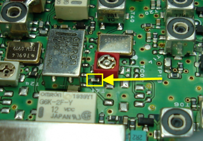
PCB graphic drawing view... 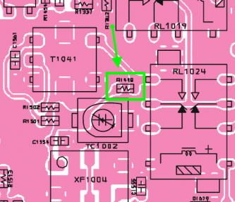
After removing the resistor, the PCB will look like this... Note the resistor pads in the yellow highlight box... 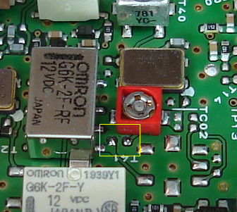
In the photo above, the pads have been cleaned with alcohol to remove the flux. This helps with inspection of the pads. BOARD PREP STEP B - CUT TRACE on T1040 Overview: In this step, we disconnect the existing 3 KHz Yaesu filter from the on-board matching network formed by C1549 and T1040. This is done by cutting the trace that runs from XF1004 to T1040. The PCB is a multi-layer construction so take care to cut only enough of the trace to break the connection. Schematic cap C1555 is 3-star marked and that means it does not exist on the board and so the trace is clear of obstructions. T1040 and C1549 also serve to allow a very precise fine-tune the output matching to the filter, which provides a very well formed passband shape. In addition, the step-up action of T1040 matches the high Z input of the following FET amp. Because of this, no additional matching network is needed on the filter side. 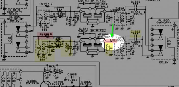
Highlighted in this picture (below) is the input connection "foot" of T1040. We are going to cut the trace right at the junction of the trace - and the solder joint. TIP: The transformer T1040 is labeled "T40" on the PCB 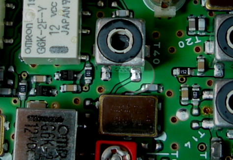
To make the cut, I used a NEW X-acto blade and took about 3 small strokes. Below, we can see the trace following the cuts. After each stroke, I tested for continuity between the filter contact point (red circle) and ground. When the trace is cut, there will be no continuity showing between the red-circle solder pad and ground. TIP: Do not make more cuts than are needed to see the break in continuity to avoid risk of damage to other PCB layers. No installer has ever reported this problem - but we don't want you to be the first! :) 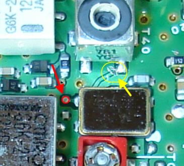
FILTER INSTALL PART 3 - FINAL ASSEMBLYAt this point, it's time to put the filter into the rig, confirm operation and secure it's final resting location. TIP: Temporally place the filter into it's resting place so you can see roughly where the wires will go, and get an idea of the clearances. FINAL ASSEMBLY STEP A - CONNECT FILTER OUTPUT COAX TO RIG PCB Overview: In this step, we are attaching the coax feed to the input of T1040. Soldering the tip of the coax to the input requires good magnification, lighting and a very sharp soldering iron tip. It's easy to create a solder bridge between the foot and the transformer casing. If you do this, it won't damage your rig - but the signal will not pass. The good news is, with lighting and magnification, the connection is pretty simple and easy to do with a steady hand. From the PCB graphic drawing, we can see the connection points for this end of the coax... 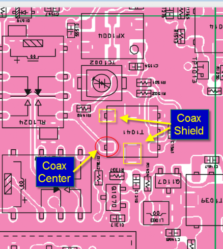
A very good sequence to follow is:
- Solder tin the T1040 input pad. The lead-free solder in the rig is tough to wet - this step helps.
- Solder tin the tip of the coax to ensure good wetting between the two.
- Trim the amount of exposed center conductor lead on the coax to about 1mm (1/16") as shown in the picture below. This helps avoid a short between the transformer foot and the case.
- Tin the side of T1040 where the PCB lettering says T40 (shown in picture at right).
- Solder the center conductor of the coax to the input of pad T1040 (below, inside the highlight circle).
TIP: The clearance between the shield of T1040 and the input lead is small when viewed without magnification. Which makes dealing with T1040 the most delicate part of the installation. Solution? Lots of light. From the sequence above, tin the tip of the coax... Bend the shield of the coax at a 90 degree shape like this so you have easy access to the tip. 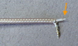
And tin both the transformer casing and the foot... 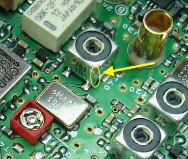
Then it's time to solder the OUTPUT coax center conductor to the foot of T40. Inspect as best you can - looking for an accidental solder short between the foot and the casing. If there is one, a touch of solder wick will clear it easily. TIP: Solder ONLY the center conductor at this point. Then inspect. But do NOT move the filter or this wire when inspecting - as it can easily become disconnected from the tiny foot solder joint. 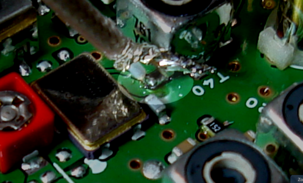
Finally, we solder the SHIELD conductor to T40 to complete the connection. 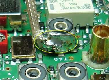
Congratulations! The hard parts of the installation are now complete. FINAL ASSEMBLY STEP B - CONNECT FILTER INPUT COAX TO RIG PCB Overview: In this step, we are attaching the coax feed to the relay source. Connection soldering points are shown here in the drawing and picture below. - The center coax connection goes to the RED CIRCLE contact point on the PCB.
- The coax shield braid can attach to either (your choice) of the YELLOW BOX contact points. Do NOT use other grounding locations.
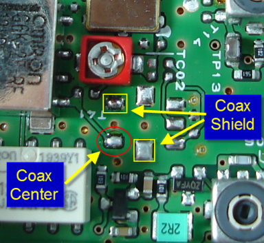
As with the output line, the sequence is about the same: - Tin the center conductor.
- Tin the shield.
- Tin the solder pads on the PCB
- Solder the center conductor of the coax to the PCB
- Solder the shield of the coax to the PCB
As with the output line, we first solder the center coax connection point as seen in the photo below being careful to center the conductor on the pad. 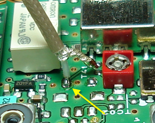
Next, solder the shield to the PCB pad. TIP: As with the output coax shield, this contact point serves as a strain relief for this coax jumper - so it should be soldered well. And because this ground point is on the PCB, it takes some heat. IMPORTANT: The picture shows this wire coming off the board vertically. However, the wire will need to lay down under the filter when it's put into position. That's not a problem if the shield solder does not wick up. In the picture here, the solder is mostly at the joint point as indicated by the yellow wire. However, if the solder wicks up, this coax can be quite stiff and it may not lay down properly.
To ensure it does lay properly, hold the wire near the PCB contact with a set of diagonal pliers. Place the tip of the pliers just above the point where the outer insulation has been removed. And with your other hand, bend the wire down - away from the mixer shield and generally toward the red trimmer cap. 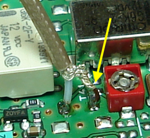
Solder directly to the PCB. DO NOT USE OTHER GROUNDING LOCATIONS At this point, the INPUT COAX should look something like this: [NOTE: The output coax is not shown connected in this photo - that's so you can clearly see the input coax connection] 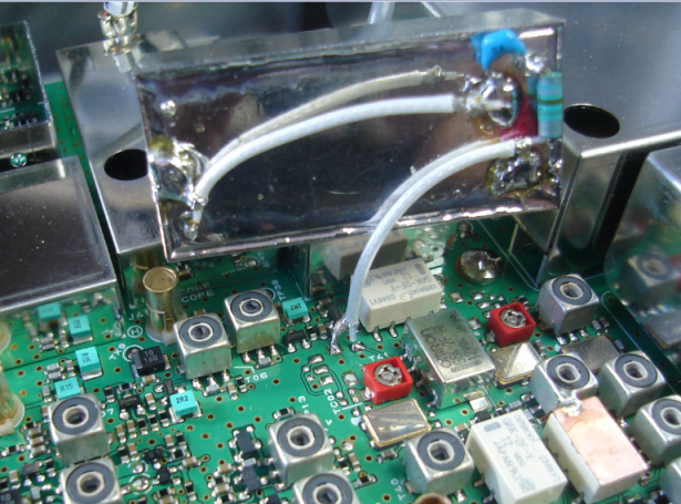
FINAL ASSEMBLY STEP C - INITIAL TESTING Time to check out the operation. Checking to make sure no tools or other items are laying on our rig... Connect AC power to the rig. And power on. TIP: In the history of the filter program, we have NEVER had a report of someone "letting the smoke out!" So don't worry. It's going to work fine... Check to ensure no tools or other things are setting on the rig. Then power on the rig along with a temporary antenna (even a short jumper wire will be acceptable). Switch between the various roofing filter positions. Check to see that you have approximately the same S-meter readings between the 6 KHz and 3 KHz switch positions. This confirms that our wiring is made properly and we don't have any shorts. You may notice some decrease in overall volume as you switch from 15 kHz, to 6 kHz, and again from 6 kHz to the NS filter in the 3 kHz position. [This is related to the noise power (as the bandwidth gets narrower, with the same peak amplitude, the overall volume sounds less) and is normal.] TIP: If the AF level in the 3 KHz roofing filter position is very very low, by comparison to the 6 kHz position, then it's most likely that the T1040 input pin connection has a tiny short to the transformer's case. Examine that connection point carefully and resolder if necessary to clear the short. This is the #1 install error. FINAL ASSEMBLY STEP D - MOUNTING FILTER IN FINAL POSITION Tilt the filter into position as shown below. Allowing the labeled side of the filter and edge to rest against the shield cans noted by the yellow arrows. IMPORTANT: The proper filter position is in FRONT of the mixer shield. **NOT ON TOP** of the mixer shield. The picture (below) shows this clearly. 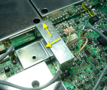
Notice the top of the filter sets even with the mixer shield. But the filter is not to be mounted on top of the mixer - otherwise, the bottom large shield plate will not set flat over the installed filter TIP: If the bottom shield sticks up a bit, double check the filter placement. It's probably sitting on the mixer case instead of in front. Note: Let the coax wires naturally lay in whatever orientation that they would prefer to follow. We want to be very careful with the coax leads out of respect for their delicate solder connections to the PCB. In prior testing, the NS filters' ultimate attenuation performance is almost completely unaffected by the wire's proximity or routing. TIP: Other mounting positions are NOT recommended. This position has a negligible impact on the passband response of the other filters shape, allows for short coax connections and provides excellent ultimate attenuation performance in-circuit. 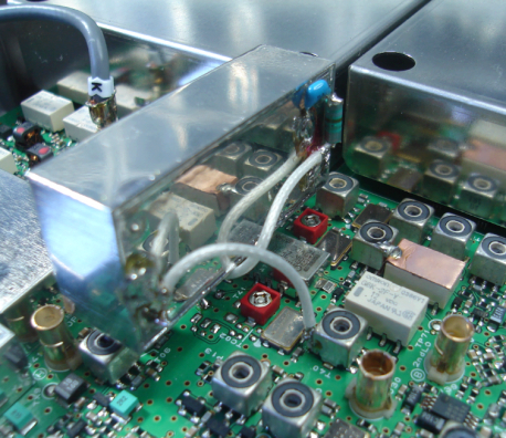
Tack-solder the corner of the shield to the filter as shown. This will require a high -heat soldering iron setting because the shield and the filter case are excellent heat sinks. This solder joint provides the filter with a good RF ground as well as holding it in place. 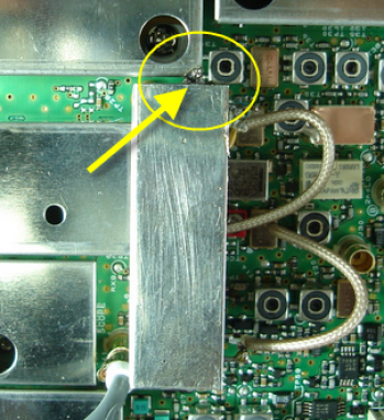
Do not add other materials onto the top or bottom of the filter. The width of the filter is designed to fit exactly between the board and the shield cover. The clearance is minimal and as a result does not provide any compressive force to the underlying PCB. TIP: If you are using the rig in a high-vibration environment, the I suggest you add one more solder tack between the top (logo side) of the filter and the mixer shield so that the filter is secured in 2 locations. At this point, the installation of the filter is complete. Congratulations! NEW: Two quick tests to help you confirm it's working as it should: 1. The S-meter reading between 6 Khz and 3Khz positions should be similar. If they are not about the same, double-check your soldering - especially the trace cut. If it all looks good, then see below on the comment regarding the 82 pf cap.
2. To hear the filter roll-off, set the rig to SSB mode. Open the DSP bandwidth to 4 Khz. Tune to a unused part of the band and turn up the volume. Toggle between the 6 Khz and 3 Khz positions and there should be a very easy to hear roll off of the higher frequency in the 3 Khz position. ADVICE BY HAMS WHO HAVE INSTALLED THE FILTER - Use a very hot, very fine-tipped soldering iron. The lead-free solder on the PCB has a higher melting temp - as much as 50C-100C higher - than traditional lead/tin solders. This means a hotter iron is helpful so the dwell time to make the connection remains short. To minimize dwell times, solder-tin each wire or connection before making the solder joint. Temperatures too low will cause excessive soldering time and potential delamination of a PCB pad. [AC0C - when doing this install, I personally set my Weller to 850F/450C when working on the rig board - this ensures the solder melts completely and quickly - so my connections can be fast.]
- Lead-free solder concerns. Yaesu recommends the use of only lead-free solder in the repair, however many hams don't have lead-free solder available. This lead-free recommendation is driven by the RoHS compliance environmental certification. However, if maintaining strict RoHS compliance is not a factor, the use of lead-containing solder is functional. I have not seen data that would suggest any drop in reliability when mixing lead-free and lead-containing solder for the connections mentioned here. The important point is that the solder temperature must be high enough to fully melt the lead-free solder.
- Check the red dot. The red dot side is where the matching net is installed. And the coax from that matching net goes to the T41 connection side. **NOT** the T40 "small foot" side. If your filter seems to work, but the loss when using the 3 KHz position seems high, check the orientation. [The installation photos have also been updated with enhanced red dots for more easy understanding based on this comment]
- If you have done the original Charlie W5VIN mod, which puts wire jumpers over the zero ohm resistors, the procedure is unchanged. One of the zero-ohm resistors is removed in the process. If you have not done this mod, it's not necessary with this filter install.
- Yes, access to the 6/15 KHz filter trimmers TC01/TC02 will be less convenient by the filter placement. However, I strongly recommend that you DO NOT relocate the filter to another position. The location specified is optimal and repositioning may create capacitive coupling and unanticipated detuning.
- "Stress again the need for proper magnification. If the parts look too small after you put your magnification device on the board, then you need to get something with a stronger magnification capability."
- Use multiple light sources to help minimize shadows. A ring magnifying lamp may provide enough, but I find in some cases using one of the small 6-LED hand-held miniature flashlights to be helpful in some cases. Use something to help position the flash light to give extra illumination to the area you are working on.
- Fluxes. Several hams have commented that installers using no-wash type of flux should be careful. These chemicals may be incompatible with the PCB and/or solders used. Rosen-core solders, and rosen type flux is safe. Cleaning the board is optional - and can be done with improperly alcohol and a old toothbrush. If you chose to use additional flux, apply it sparingly.
- The coax supplied for the installation is of a Teflon-type. Which means it has excellent temperature resistance. It also means you must have a very sharp striping tool to ensure a clean cut. You may need to strip the cable a couple of times before getting a nice clean result. As a result, the lengths of coax now being sent are a bit longer to allow for this. The most time-consuming part of the install is generally the coax preparation.
- Short coax lengths and replacement of SMD devices make for a very nice picture - but the performance is the same as with somewhat longer length coax runs and the through-hole components supplied. So don't worry about getting the last few mm of coax length removed - it is far easier to perform this install with coax of adequate length. And remember, once the cover is on the rig, no one will ever know you used an extra 5 mm of coax! :)
- When installing the filter, take care that the filter input side coax and inductor joint does not short against the filter. A bit of heat shrink can be helpful here.
Comments on Alignment - ALIGNMENT IS NOT REQUIREDThe Yaesu manual specifies the S-meter calibration sequence to be performed in the 6 KHz position. Generally the insertion loss of the 6 KHz and the new NS filter will be about the same and the S-meter indication will be about the same. The peak audio levels will be very similar as well - in fact, depending on the performance of the Yaesu 3 kHz filter in your rig, you may notice a slight increase in the signal levels when using the new NS filter. The output filter matching provided with the stock alignment setting will be satisfactory without further adjustment and will be at least as good as the original filter performance.
Unlike rigs of old, there is no need for periodic rig realignment. In fact, its pretty easy to create more problems in the alignment process than there is potential upside benefit. Further, there are errors in the alignment procedure as published (even in the latest revision E) of the TS... -------------------- TIP: About the 82 pf cap. In a few cases, hams have seen higher than expected losses with the NS filter compared to the 6 KHz filter. Removing the 82 pf cap resulted in normal operation.
--------------------- For individuals with the proper capability, the MCF alignment steps are given on page ALIGNMENT-4 of the service manual and can be followed. In the case of the 3KHz filter, adjustment is ONLY made to T1040 as TC1002 is not part of the circuit following the NS install. For individuals with a spectrum analyzer functional at 450 KHz, connection to the 2nd IF as explained in the following link allows real-time examination of the filter passband. http://www.ac0c.com/main/page_ft2k_roofing_filters_ft2000_rig_plots.html With tiny adjustments of T1040, precision tuning of the filter's top 3db passband is possible. Adjust the SA so that you are looking at just the top 10db of the filter response or less. The signal strength alignment in the TS will set T1040 to the correct range. And then with the SA, make sweeps and fine tune T1040 in tiny increments of perhaps 1/10th turn to find the ideal trim point where filter symmetry and passband is optimized. >>>>> Suggestions? Please direct comments regarding page to jeff -at- ac0c -dot- com <<<<< |