When the FT-2000 was first released, there were several reports of preamp failures. While the data was not very clear, the general trend seemed to be that many users had a separate antenna for RX enabled. I've never been concerned about this because I don't use a separate receive antenna. However, I'm now looking into some tests with a loop for the low bands so the subject has come up again. After digging around and examining the service manual, the details can be gathered for what needs to be adjusted. Shown here is a summary of the modifications made to the ANT board (the PCB the coax connectors are mounted on) and the MAIN board (where the preamps are located). These values are found in the latest version of the Yaesu FT-2000 service manual. The result of these changes serves to lower the threshold at which the protection is engaged. And to protect the mixers on the two receivers. Component values are given here. Resistors are of the 0603 size. Capacitors are 0804, I believe. The usual advice applies. These are very small parts. If you are not versed in SMT work, I would recommend getting someone who is to do the work for you in order to avoid potential trouble through an accident. Some board removal tips follow at the end to assist in the PCB removal. Be careful! And good luck... 73/jeff/ac0c DETERMINING THE LOT NUMBER FROM THE SERIAL NUMBER Yaesu has made several incremental improvements in the front end toughness over the production history. To see which of the component changes mentioned below apply to your rig, determine the lot number. FT-2000 serial number format: YY LL RRRR Y - Year of manufacture M - Coded value for month shifted 2 in the alphabit - so "C" = Jan, "D" = Feb, etc... LL - Lot or run number RRRR - Unit number within the lot ANT BOARD CHANGES The changes to the antenna board are shown here. If your rig's lot number is in the range shown, that component change would be recommended. Item | Old value | New Value | Applies to Lot # | C2704 | 22 pf | remove | 1-31 | C2705 | 2p | 3p | 1-31 | C2707 | 0.047 uF | 0.001 uF | 1-31 | R2705 | 100K | 4.7K | 1-42 | R2707 | 22 | 0 (short) | 1-42 | R2713 | 56/5W | 39/5W | 1-26 |
ANT UNIT location 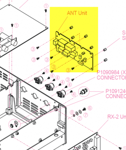
ANT Unit schematic showing the mod locations. CLICK on Schematic for better view. 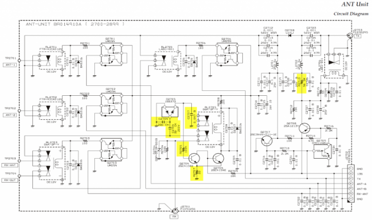
ANT UNIT mod part locations 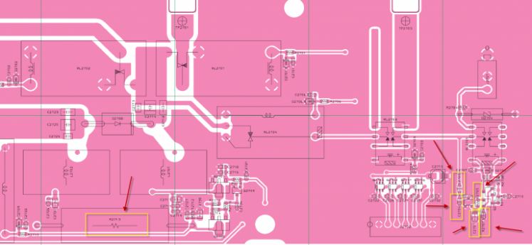
MAIN RX PREAMP CHANGESThe changes to the main RX preamp board are shown here. If your rig's lot number is in the range shown, that component change would be recommended. Item | Old Value | New Value | Applies to Lot # | R1180 | 150 | 47 | 1-44 | R1181 | 150 | 47 | 1-44 | R1196 | 1K | 330 | 1-44 | R1198 | 1K | 330 | 1-44 |
Unlike the ANT unit, the preamp mods are on the main board. Work takes place in the area of the board enclosed by the yellow box below. A close-up of the area with part locations is given further down the page... 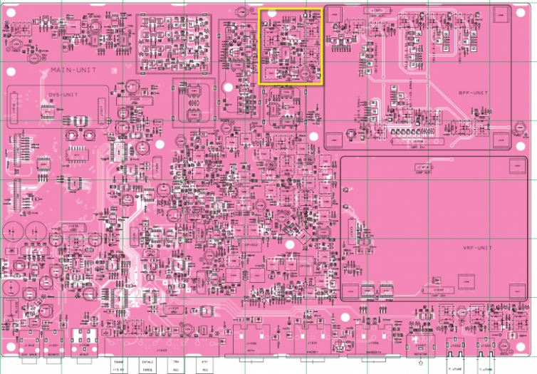
Preamp mod locations in the schematic here. 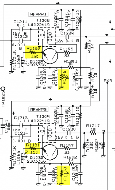
Preamp mod component locations 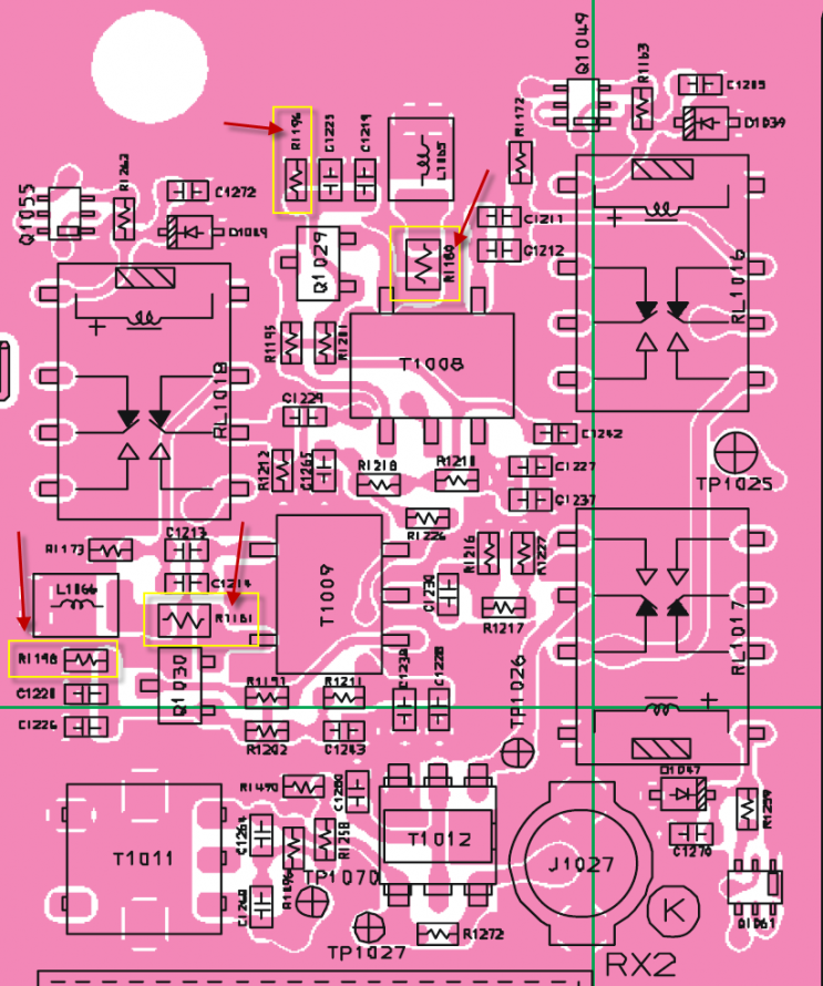
Board Removal Suggestions 1. Take out the RX coax feed plug and tuck it out of the way
2. Unsolder all the SO236 center pins and the ground tinned wires from the board and bend out at about a 45 degree angle
3. Unsolder the BNC ground and bend away, leaving the BNC center attached
4. Remove the six mounting screws from the back, applying a bit of heat to the center BNC connection where it touches the PCB - in order to let the board drop away
5. Wiggle the board out at an angle leaning forwards and up at the TX phono end - disconnect the cable when its clear of the tuner box. Raise the board up disconnect the logic connection cable to free the board. |