I wanted to take a look at the characteristics of the roofing filters used in the FT-9000 to see how they performed vs. the filters found in the FT-2000. Part of this interest was driven by curiosity of how the $10,000 FT-9000 roofing filters performed. Generally speaking, the filter performance in the up-conversion rigs vs. the claimed values tend to be nonsense. Would it be the same for the FT-9000? Another part of the interest follows an observation that the 1st IF in the FT-9000 main RX is the same frequency as the 1st IF in the FT-2000 sub RX. Could the filters in the FT-9000 be brought into service as a performance mod for the FT-2000 sub? The IMDDR3 performance of the FT-9000 is pretty good - around 85-88 db - but that alone does not answer the question. A lot of factors influence the IMDDR3 performance of a rig, the roof being just one. However, the stock 15 KHz wide roof of the FT-2000 sub offers very little front end protection especially when you consider how many CW signals can fit into a 15 KHz bandwidth during your favorite contest! REASONING
The 1st IF of the FT-9000 is at a lower frequency than the FT-2000, 40.455 vs. 69.450. In general terms, the difficulty of building filters is an exponential one with frequency. While numerically 40 MHz and 70 MHz are less than 2:1 in a linear frequency ratio, from a filter builder's standpoint, they are worlds apart. We have seen in the case of the FT-2000 that the 3 KHz MCF is actually a 6-7 KHz bandwidth. If the theory is correct, the job of building a 40 MHz filter should be much easier - and in comparison, the actual performance vs. target bandwidth of this lower frequency filter should be improved vs. it's higher frequency relative. The only way to know is to put the filters on the bench. We needed samples of the filter and those had to be ordered from Yaesu. The ordering process was easy and about 2 months later, they arrived. SMALL PARTSWow, these filters are small in size, about 5x7 SMT packages. Of course you can see them mounted on the FT-2000 main board, but it's not until you have the filter in your hand that you appreciate just how small the little beasts are! A simple test platform was built up using a copper mesh ground plane with short connections to the BNC cables. This arrangement allowed room for changing other components (for example, the filter cap value) to see their results. I doubt Paul N2PK would approve of this test layout - but our goal was to get some simple and quick test results to see if this idea had merit. If the filter was not an improvement, we could know immediately. 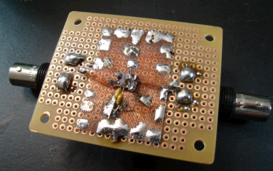
PRELIMINARY TEST RESULTSAgainst that backdrop, it was a big surprise when the VNA measured the filter at about 3.3 KHz. Hea, a Yaesu 3K roof that is - yes - 3K wide? Yes ladies and gentlemen, I am here today to say it's true. The FT-9K roofs measure just as advertised. No wonder those FT-9000 guys are so quiet on this issue. Their filters work just fine, thank you!!! In addition to being of the proper bandwidth, the centering of the filter is, in comparison to the FT-2000 roof, much better. 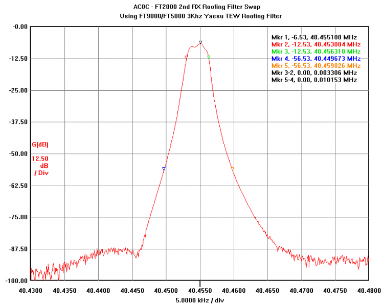
SURPRISES AND SETBACKS The 15 KHz roof was tested as well. I had expected the 15 KHz filter to measure a bit differently but the huge ripple amounts in the passband suggested a much larger impedance mismatch than with the 3 KHz filter 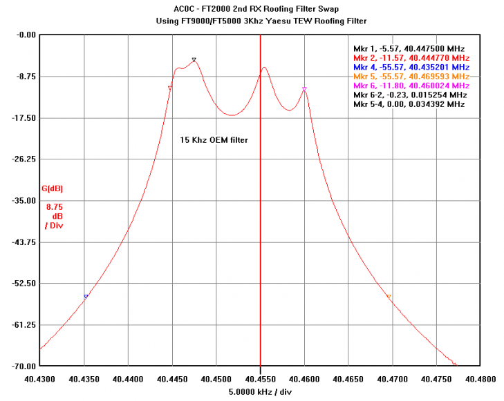
From the work on the 2K, I suspect the natural impedance of the 3/6 KHz 69.45 MHz filters is around 25-30 ohms. But unlike the more or less low ripple case of the earlier plot, here we have gigantic swings. Time to take a closer look at the schematic... The filter cap values scale with filter width. And the other cap values in the circuit, as well as the topology, is the same between all 3 filters in the 9K. So what remains? Transformers... 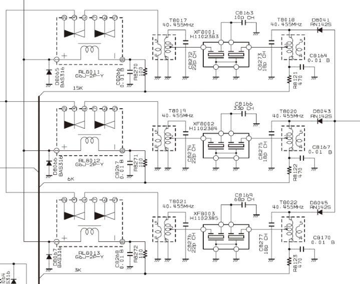
Looking at the part number for the 3 filters, I had expected to see the same P/N for each. Alas, they are not. And I think this is the confirmation behind the theory. The 15 KHz roofs probably have a different impedance and a different matching ratio is needed as a result. The table suggests the 6 KHz filters are different again. 
So the next step will be to get samples of the 3 KHz filter transformers and take the next step. Closer to the objective - but not quite there yet... Filter Swap ProcessI received the transformers from Yaesu and got them swapped out. Removal of the filter and transformers was via hot air. A couple of caps were moved in the process and I replaced them. The old filter is seen now sitting on the mixer shield - and the new one in the center of picture. 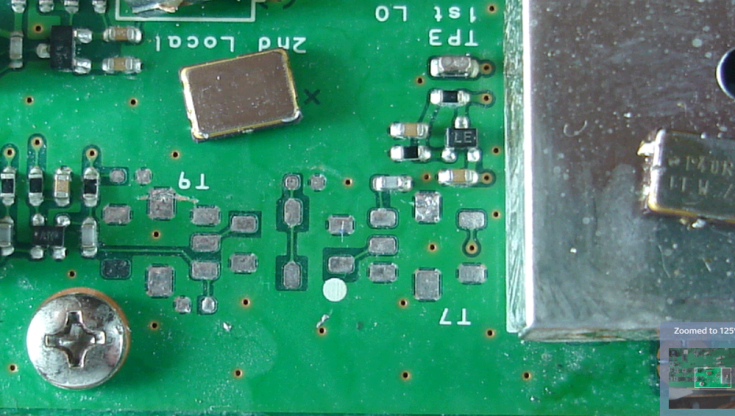
The new transformers for the 9K are quite a lot larger than the size that is specified for the 2K. However, the pin footprints and center spacings are pretty close and so they could be mounted with a bit of care. And the board has plenty of vertical clearance to accommodate the taller transformers. 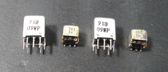 I soldered the new 40F 3KHz filter in first because it does not have visible mounting pins and examination for proper soldering can be tough when the other parts are in the way. Next I fitted the first transformer near the mixer – soldering the pins adjacent the mixer can side first. Then working outward from there. The mounted parts, prior to deflux, are shown here. 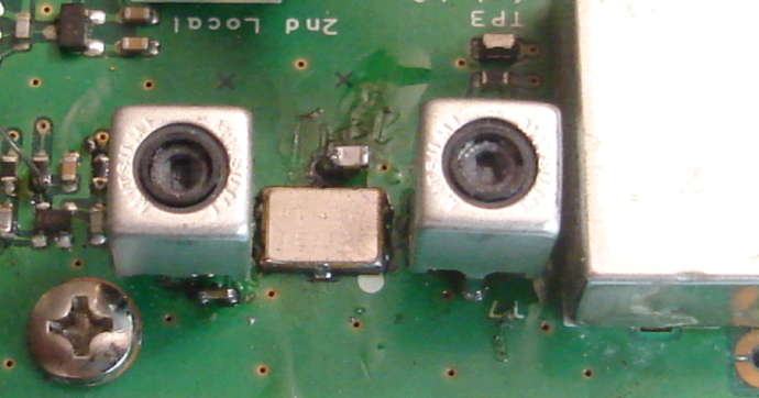
Filter Swap ProcessSo what does all this work do for the 1st IF? The plots below were taken from 2nd IF at R4645 (zero ohm resistor feeding the PIN diodes just prior to the 2nd IF filter bank) via a high-z probe. This is a couple of L/C steps away from the 2nd mixer. Mode tested is CWL - and to avoid the 2nd IF filtering from contaminating the results, the 2nd IF's 6 KHz filter was hot-wired to be selected for the test resulting in minimally impact the plot… Filter cap value of 62 pF turned out to be the optimal value. Using this measuring method, the -6db points are about 3.85 KHz wide. Below is a close-in response curve focusing on the top 12 db of the response. The passband exhibits only a minor amount of ripple. 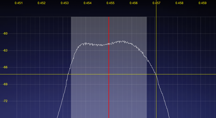
The funny shape on the right side of the filter is due to the SDR’s LO at 460.7 KHz. In actual performance, the filter shape continues on downward (purple line). The noise floor shown here is not that of the rig - it's a byproduct of the amplified probe. Contrast this curve with the original 15 KHz filter plot - which would include the entire spectrum edge to edge of the frequency range below... Very nice indeed. 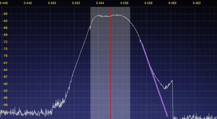 Improvement in IMDDR3 Performance I did not have good pre-modification DR3 measurements. So I compared the DR3 performance by comparing the modified rig (lot #24) and another rig of similar vintage (lot #26). The sum marry results are: Offset | 5 KHz DR3 | 5 KHz DR3 | 5 KHz | 2 KHz DR3 | 2 KHz DR3 | 2 KHz | F+/F- | Stock | Mod | Improvement | Stock | Mod | Improvement | Low | 77 db | 90 db | +13 db | 65 db | 78 db | +13 db | High | 66 db | 91 db | +25 db | 64 db | 79 db | +15 db |
Tests were made with using the 300 Hz Inrad / Collins filter. DR3 values are about 3db less with the 500 Hz XF-115C Yaesu filter. There is only a 1-2 db improvement in DR3 between the stock 1200 Hz filter vs. the 300 Hz Inrad / Collins filter. However, these filters are found in the second IF (at 455 KHz) and serve more as selectivity rather than IMD product prevention filtering. The +12 db difference in improvement between the low and high side readings is due to the off-center characteristic of the stock filter on the unmodified receiver. In a perfectly centered filter, about 7.5 KHz of passband should be present on either side of the DR3 tone. So the passband would contain one fundamental tone and the IMD mixing product. The second fundamental tone would be attenuated somewhat as that tone would fall on the filter's transition band. However, with the filter being off center, the attenuation the rig sees is asymmetric - in one combination there is much more attenuation - and in the other, much less. The replacement 3 KHz filter has some slight misalignment as well, however, it's very narrow compared to the 15 KHz stock filter and offers some amount of attenuation to the outlying fundamental in both the high and low side measurement cases - hence the measured DR3 numbers are quite similar. Noise Floor Comments The sub RX has quite a high noise level with the antenna disconnected. My thinking is there are 4 possible sources of the noise: 1.IF amps 2.AF amp 3.Mixer byproducts 4.LO noise I did some testing of the IF amps – adjusting the gain manually via the AGC line and looking at the SNR of a weak signal on the AF scope. The AF amp can be considered clean – when the IF gain is turned down, the AF output is pretty quiet. I think this suggests the AF chain is not the primary cause. And The constant SNR with varying levels of IF chain gain suggests the IF amps are not the source. That leaves the mixers and the LO as the potential noise sources. Here the sources can be narrowed considerably. Pulling the 2nd IF mixer LO results in a moderate change in the noise level and so I think the issue is specific to the 3rd mixer or the 3rd mixer LO feed. I don’t have a way directly to test the LO but the spectrum looks pretty clean (the scale is correct for the SNR but the absolute level is not calibrated) – with the noise about 90-100db below the carrier. The floor here is likely the limit of the sound card and not necessarily that of the LO source. I can do one other test – replace the 2nd LO and 3rd LO with the Si570 sig gen to see if that improves things. But beyond this, I am out of ideas at this point. After quite a lot of toying about on the bench, I decided that the most effective way of addressing the rig noise was to modify the AF passband to roll off the top end. But that's a story for another page... Click HERE for AF Passband Adjustments |