
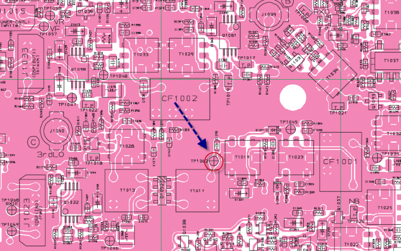
Roofing Filter Measurements - At the Rig LevelFilter performance can be measured independently and will be quite close if the matching is well executed. However, we cannot assume that to always be the case. And in the FT-2000, there are good reasons to conclude this is not the case. So today we have taken a different path. This data shown below measures the roofing filter performance at the rig level. By injecting signals at the antenna, and then pulling the spectrum directly from the 2nd IF, we can measure the performance of the filter is it works with the rig as a whole. Prior analysis had been performed with the filter connected directly to a VNA and indirectly suggested final rig performance. With this method, we can in fact measure it directly. I believe that the only other data to be gathered are the most excellent and original plots from I4SBX. Presented here are scans of each filter, looking at 6db and 80 db. The 6 db scale allows for careful analysis of the passband. And the larger scale, for determining the overall shape. The horizontal scale is at a high degree of magnification so we can get additional measurements for the 6db and 60 db bandwidths. Generally we can expect the bandwidth calculations for the rig as a whole to be slightly wider than the individual filter because the entire rig becomes a part of the filter, to some extent. And by looking at one filter vs. the next, under the same measurement method, we have a very reliable comparison technique. Measurement TopologyThe N2PK serves as our sweep generator source. The N2PK is feed through a step attenuator and then into the rig. The plots made here were taken with a 7.0 MHz input signal. The spectrum feed was captured from this point in the 2nd IF, just prior to the 3rd mixer. The sample point is removed from the 1st IF by several conversion strips and the 1st IF and provides a way to measure without disturbing the shape of the passband. Schematic and board locations are shown below: 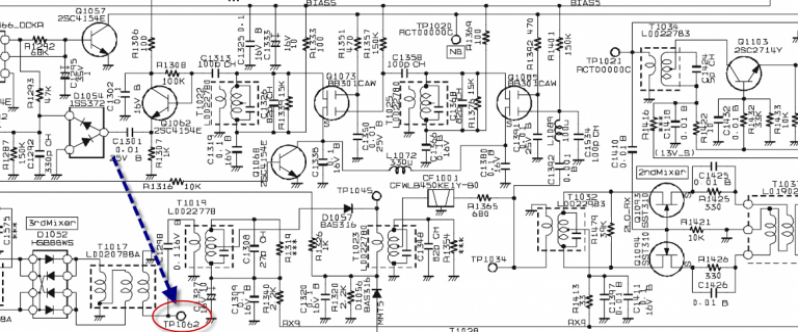
NS Prototype SN002 This filter scan is the first done with the preliminary matching LC network installed. We can expect some change in the passband ripple as a result of any matching work done - and what we want to look at his how dramatic is the impact. The matching network is needed to recover about a 3 db overall signal level loss due to the unusual termination in the rig for the stock filters. Here we can see the ripple is extremely low at less than 1db. Considering this is a VHF filter of 3 KHz width, this is amazing performance. 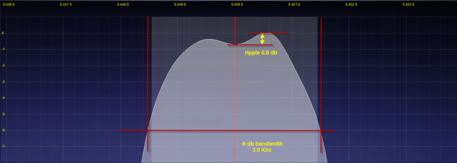
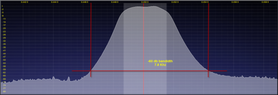
From the rig scans, we come up with these statistics from the prototype filter: - -6 db @ 3.0 KHz
- -60 db @ 7.8 KHz
- SF: 2.6
This is excellent agreement with the NS measured -6db point of 2.95 KHz. NOTE: The plot is for the prototype filter, of course. The production filters will exhibit passband widths of about 2.4 KHz @ -6db, and 6 KHz @ -60 db. Quite a significant further improvement over and beyond the performance of this wider prototype sample. 6 KHz Yaesu OEM FilterLooking at the top of the 6 KHz filter's passband, we observe about 2.2 db of ripple and a 7.4 KHz passband @ 6 KHz. 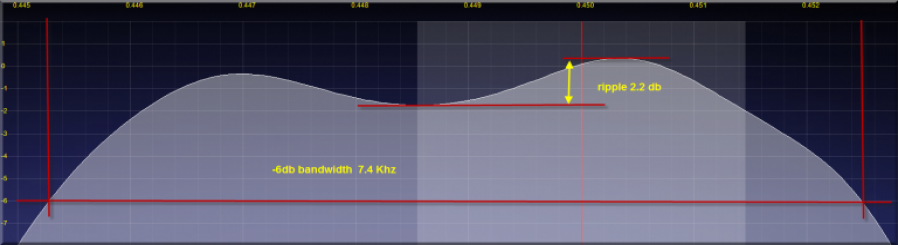
The shape at a larger view is unremarkable. The small peak shown on the right side is a spur related to the measurement equipment and not part of the actual filter response. 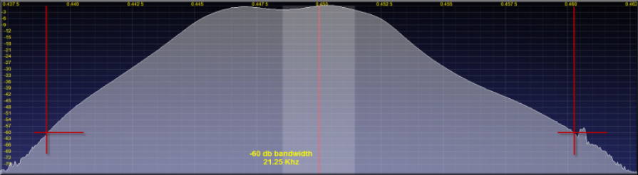
Final statistics for the filter from this measurement series are shown below. Overall, a nice plot for a very low cost filter - considering it is a bit wider than it should be. - -6 db @ 7.4 KHz
- -60 db @ 21.25 KHz
- SF: 2.87
15 KHz Yaesu OEM Filter Due to a strange twist of the measurement rules, the 15 KHz filter can be said to really be 8.4 KHz. Can that really be the case? 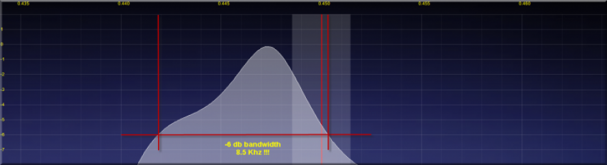
Unfortunately, not... Looking at the top 12 db, we find the excitement of the initial -6db measurement to be nothing more than a measurement fluke related to the uneven ripple characteristic of the passband. 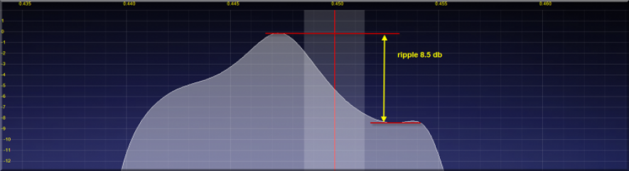
I did not attempt to measure the -60 db point on this filter. We can use the very scientific description of this filter as "amazingly wide" and know that is close to accurate. :) 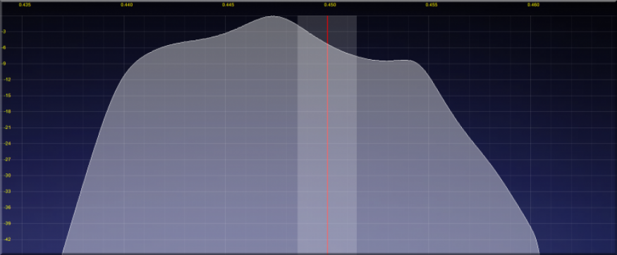
|