The AC0C NS roofing filter can be installed into the FT-950 with excellent results. And the FT-950's PCB layout makes the installation simple. Hams Providing NS Filter Install Services - CLICK HERE Shown here are summary instructions for the installation. The area of interest is shown here in the yellow box. 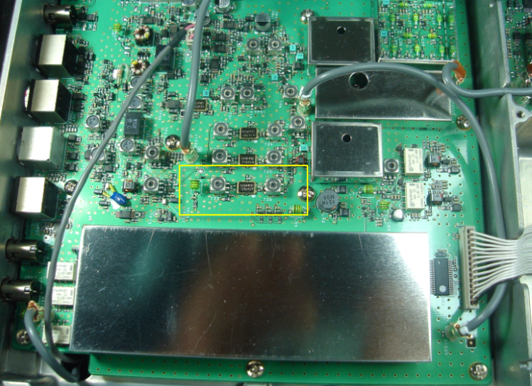
STEP 1 - remove these two small caps.A. Save them for later - you will need to mount them again after the coax is installed.
B. They are NOT the same value. So you must keep them SEPERATE. Avoid mixing. These caps must be removed because it is very difficult to solder to the transformer center foot connection point due to the cap height. 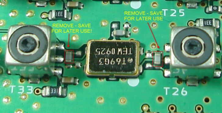

Note: The PCB photos are 180 degrees rotated from the schematic layout. This was done so the PCB lettering would be easier to reference - and because the schematic is mostly the same (symetrical). STEP 2 - Cut the 2 PCB tracesCut at the point indicated by the yellow line inside the red circle as shown here. Use the same continuity test method explained on the FT-2000 installation procedure. 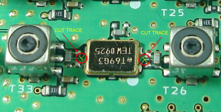

STEP 3 - Solder coax to the PCBSolder the coax center conductor to the center pads of T33 and T26. Solder the coax shield to the transformer casing. Observe good VHF RF practices here - and keep the exposed center conductor lengths short. 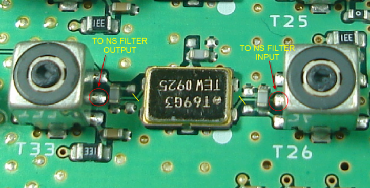

The lead lengths shown in this photo here should be considered the MAXIMUM. The shorter the exposed center lead, the better will be the ultimate attenuation provided by the filter. 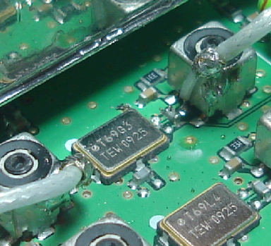
STEP 4 - Replace the caps previously removed in STEP 2 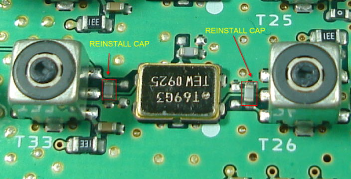
STEP 5 - Mount a 43 pF cap in series with the filter output and connect the coax A leaded or SMT part can be used. A SMT 1206 cap was used in this example (yellow box). Keep the exposed center conductor of the coax short. Solder directly to the filter case - do not use the filter ground pin 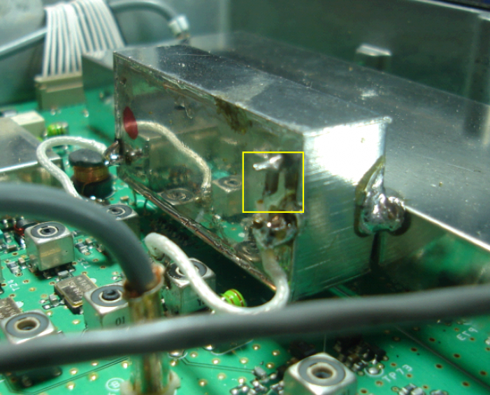
STEP 6 - Solder the NS filter to the adjacent shield 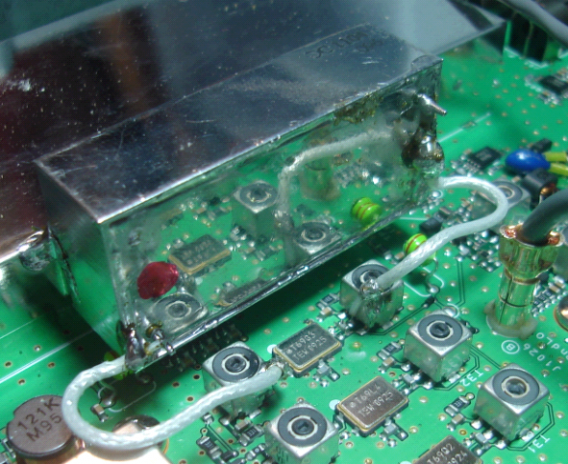
STEP 7 - OPTIONAL: trim T33 and T26 for maximum signal levelDo this ONLY if you have an insulated adjustment tool of the correct size. Using an incorrect size adjustment tool can result in damage to the transformer. 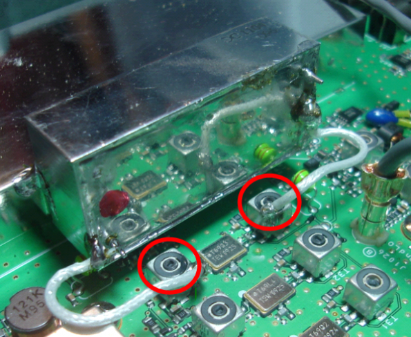
|