Old School Active Filter Sound for the FT-2000 One of my favorite features of the FT-2000 is the APF. The APF is engaged in CW, by pressing on the CONT button and holding in for a couple of seconds. It brings a "peaky" characteristic to the sound of the rig and makes CW operation a real joy. The first time I used the APF, I thought how it reminded me of an active filter. As a young ham without money for new rigs or even crystal filters for the old ones, I was drawn to the magic of active filters. With an op amp, a few caps and a few resistors, selectivity could be had on the cheap. That interest remained with me - and to this date, I continue to be interested in how filters of all types can affect the sound of a rig and increase the operators enjoyment. The DSP filtering in the FT-2000 is a huge step beyond the old active filter technology for several reasons. The DSP works at the IF level which means the AGC loop is part of the system. With AF based active filters, out of passband signals would still create AGC pumping. By moving the DSP to the IF level, Yaesu is able to largely avoids this. And DSP based filters have fantastic slopes and flat passbands with little group delay variation in comparison to active filters. Compared to an active filter, the adjust-ability and shape are a real winner for the user. But as with any filter, the shape is only magic if it's what we need to do the job. I had not seen any published work on the actual characteristics of the current Yaesu lineup. And the APF is very interesting to me because it's a perfect fit with the new roofing filter. At 2.4 KHz, the new roof works great for both CW and SSB. But the role of the roof is not single-signal selectivity - it's overload prevention. We still need the DSP and other filtering methods to give us that magic single-signal note coming out of the speaker. Of course, nothing beats crystal filters for serious selectivity work - but that's a project for another day... Today, let's look at the DSP filtering in the rig. FirmwareThe DSP functions execute the code functions specified by Yaesu in the firmware. For this test, firmware combination versions 11.53/1.49 were used. Other versions of firmware may provide different results. Function variation with firmware would be an interesting area for later investigation. Variables 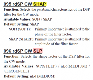 In looking at the DSP response, the expected variables were the two menu settings (SHAPE and SLOPE), the width knob, and the contour/APF modes. A related function, NOTCH, is included at the end of the In looking at the DSP response, the expected variables were the two menu settings (SHAPE and SLOPE), the width knob, and the contour/APF modes. A related function, NOTCH, is included at the end of the
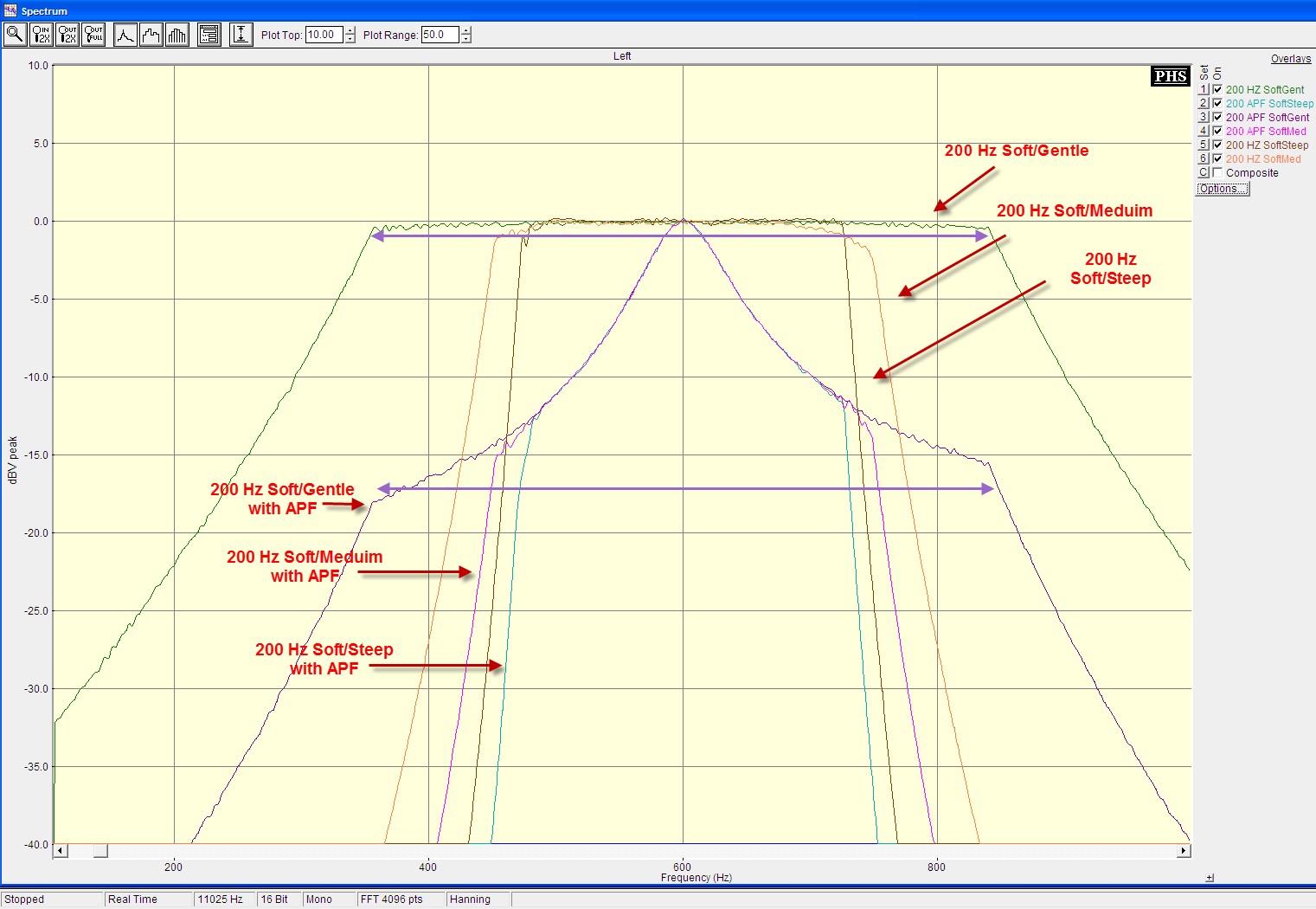
The two menu settings are the SHAPE and SLOPE. Some comments on these menu settings: SLOPE: The slope results in a much faster roll off as would be expected. However, more aggressive settings also result in a narrower passband. SHAPE: The Yaesu description talks about phase vs. amplitude and there is likely some other effect of the filter (an IIR vs. FIR implementation, for example). I looked at the stead-state amplitude effects only and the differences between the two are only a slight rounding of the corners of the passband edges. The SOFT setting is probably the better selection as I feel this has less ringing at very narrow bandwidths although this conclusion should be tested first. The APF feature came out with the PEP program and it's not documented in the original operation manual. Because of the more narrow bandwidth, the rig's MDS is improved about 6db with the APF engaged. APF is closely related to the CONTOUR function. In fact, APF, as we will see below, is actually a special case of one CONTOUR setting combinations. What's Automatic about the Automatic Peak Filtering? The center frequency of the APF is fixed and is equal to the spot frequency. And before PEP, the contour center frequency was not indicated in a meaningful way resulting in a very difficult tuning for the proper center frequency - and the trouble when the operator would accidentally bump the contour knob as often happens when adjusting the DNR. APF Filter ShapeThe first step to figuring out what the APF is doing was to sweep a signal into the rig and look at the AF response. That was harder than I thought because there are a lot of interactions with respect to filter width set by the operator, in addition to the menu SHAPE and SLOPE options. Test conditions initially were S9+30 input signal, IPO, 15KHz ROOF, CW-LSB, 3.5 MHz, and IF filter width set to 200 Hz. The strong signal level was chosen to ensure we have a good SNR. The wide roof ensures that no part of the front end "colors" the frequency response. Starting with the APF in the OFF position (not engaged)... On the top, right of the graph below, we can see the effects of the SHAPE menu setting. Changes to this menu setting also shows some interaction with bandwidth - steeper bandwidths result in narrower overall filter widths. More on this later. When the APF is engaged, the response changes from the "square" shape to one of a triangle-shaped response. The resulting overall response becomes a combination of the two. For example, consider the 200 Hz Soft/Gentle combination (purple arrows).
- With the APF *not* engaged, the response is flat top shaped as indicated by the top purple arrow.
- When the APF is engaged, a triangle peak-shaped response extends about -18dbc and is automatically centered at the spot frequency.
- The flat top shape resumes at the -18dbc point, and continues with the same shape factor (slope) as the filter without the APF engaged
Notice here that the peak signal level remains the same. I have seen comments where users report the APF mode as being too quiet - and that they cannot hear the band - that is true - the effect of the APF is to limit the bandwidth on the top 15 db of the filter response. If the signal is centered to the spot frequency, the actual volume OF THAT SIGNAL will be unchained with or without the APF. All signals above and below that, will be pushed down. Which means the effective noise bandwidth is reduced. Wonderful! NOTE: CLICK graphs to download full-size clear plots 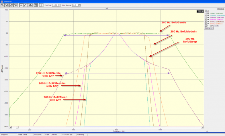
How does Yaesu achieve this magic? Here's the old school secret. The peak effect offered by the APF is actually very simple. Some experimentation in a filter design program (Shematica's Filter Wiz Pro) rivals the secret behind the APF magic. The triangle shaped portion of the APF curve looks like it is simply the DSP implementation of a basic 2-pole band pass filter. As confirmation of that, compare the plot below to the APF section on the rig plots in the graph above. Note that this graph is an almost perfect fit with what we see on the APF curve. From the simulation, filter details for the filter are: Q=9, Fpb=35 Hz @ 1db. 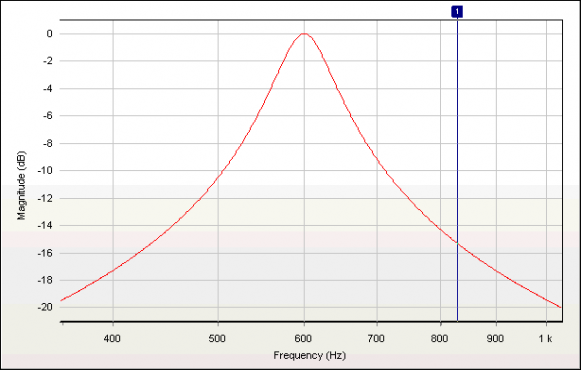
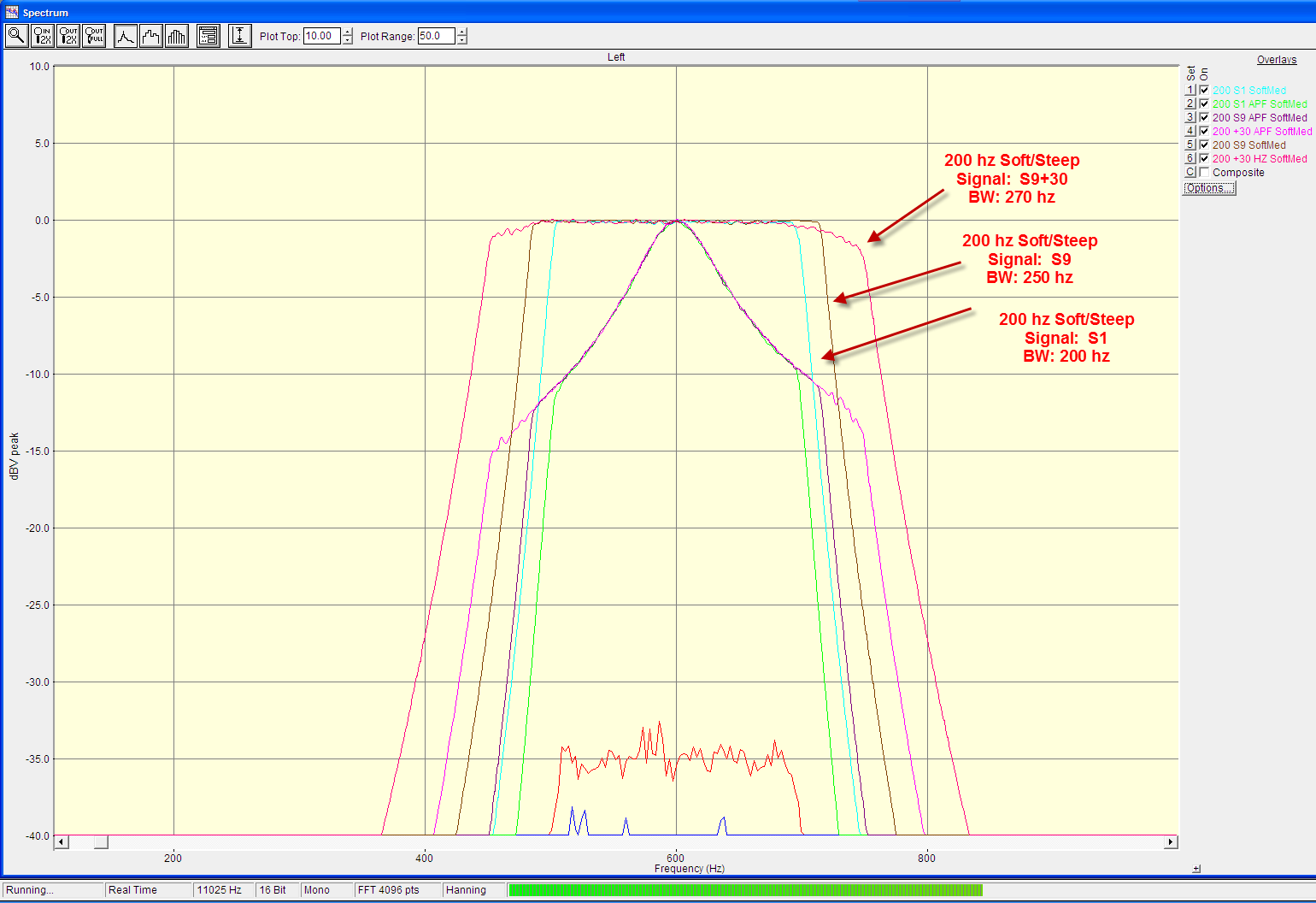
It's hard to believe but these graphs are confirming my first impressions. A little bit of "old school" active filter shape in the passband really can make magic! For the Yaesu firmware wish list: As a personal operation preference, I would love to see Yaesu offer a little bit of adjust-ability to the APF mode. Specifically, allow the user to have some gain added - so that when the APF is engaged, the overall volume of the rig is increased a bit. The reason for this is that I tend to operate with the APF engaged all the time, in CW. And then use the bandwidth control to narrow down the response after I find the signal I am looking for. That means that sometimes weak signals away from the spot frequency are difficult to hear. I compensate by increasing the AF gain (volume) level until I find the signal of interest, then reduce the DSP bandwidth control to give me the single signal effect - and then touch up the AF gain. If the APF mode provided perhaps a 6db of AF gain when engaged, I believe the user experience would be much better. The exact level, if menu adjustable, would be of course optimal! Filter Bandwidth vs. Signal LevelThe rig's DSP features an effective bandwidth which varies with input signal strength. I don't think this is a operational issue (complaint) - but the basis for the behavior does serve to "peak" my technical curiosity adding to a long list of "I wonder why they did it that way" questions. :) At low signal levels, the passband tracks very close to the indicated value shown on the rig as the bandwidth knob is rotated. However, as signal levels increase, the bandwidth response widens - and at the highest signal strengths, the net increase in bandwidth is about 30% of additional width. The graph below illustrate the findings. Bandwidth measurements were taken from the screen and do consider the slight filter rounding in the "soft" mode. The bandwidth widening effect seems to be consistent regardless of the other rig filter settings . In this example here, we consider the 200 Hz width setting, under 3 input levels. Note the effect is consistent with or without the APF engaged. [NOTE ON THE GRAPHS - Ignore the noise lines in the bottom center of the graphs - that's not part of the actual rig response. And the irregularities of the filter plot don't exist in reality - they are in fact quite smooth - what you see here is a side effect of the measurement method used] 
The 500 Hz width setting, under 3 input levels: 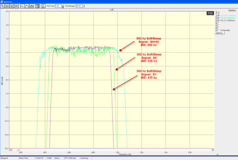
For the Yaesu firmware wish list: As a practical matter, I don't think the filter slope is very critical after the first perhaps 20 db if we are talking about general contest or DX work. But perhaps a better way to provide increased utility would be to have user-adjustable ultimate attenuation in the stopband. I notice that Flex is now starting to advertise how perfectly vertical their filter "brick wall" response is. While it's very nice for show and tell to visiting hams, generally an operator, especially with CW, wants to be able to hear the other stations above/below with some amount of amplitude. In fact, the PickAStar group with filter legend Bill Carver has added a very interesting feature where the ultimate attenuation of the filter is adjustable. In most rigs, the filter attenuation continues down to the limit of the rig's DSP dynamic range (around 60-100db, depending). The FT2000's DSP has a dynamic range of around 90db (from the rear panel AF OUT jack) - the slope is not vertical, but it's tremendously deep. Personally, for CW work, I almost never need to move the passband (using the SHIFT control). If Yaesu were to add in this feature tied to the SHIFT control (perhaps pressing A+adjusting the SHIFT), that would be a very useful tool indeed! Contour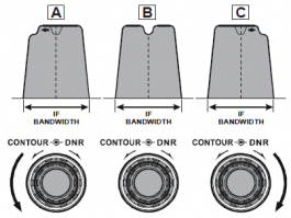 The APF feature is not very useful to the SSB operator. And here the CONTOUR function comes to play. Yaesu's operation manual does explain the function of the contour control pretty well, and presented here below are some graphs to help us put some engineering values to these various setting numbers. The APF feature is not very useful to the SSB operator. And here the CONTOUR function comes to play. Yaesu's operation manual does explain the function of the contour control pretty well, and presented here below are some graphs to help us put some engineering values to these various setting numbers.
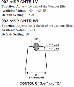
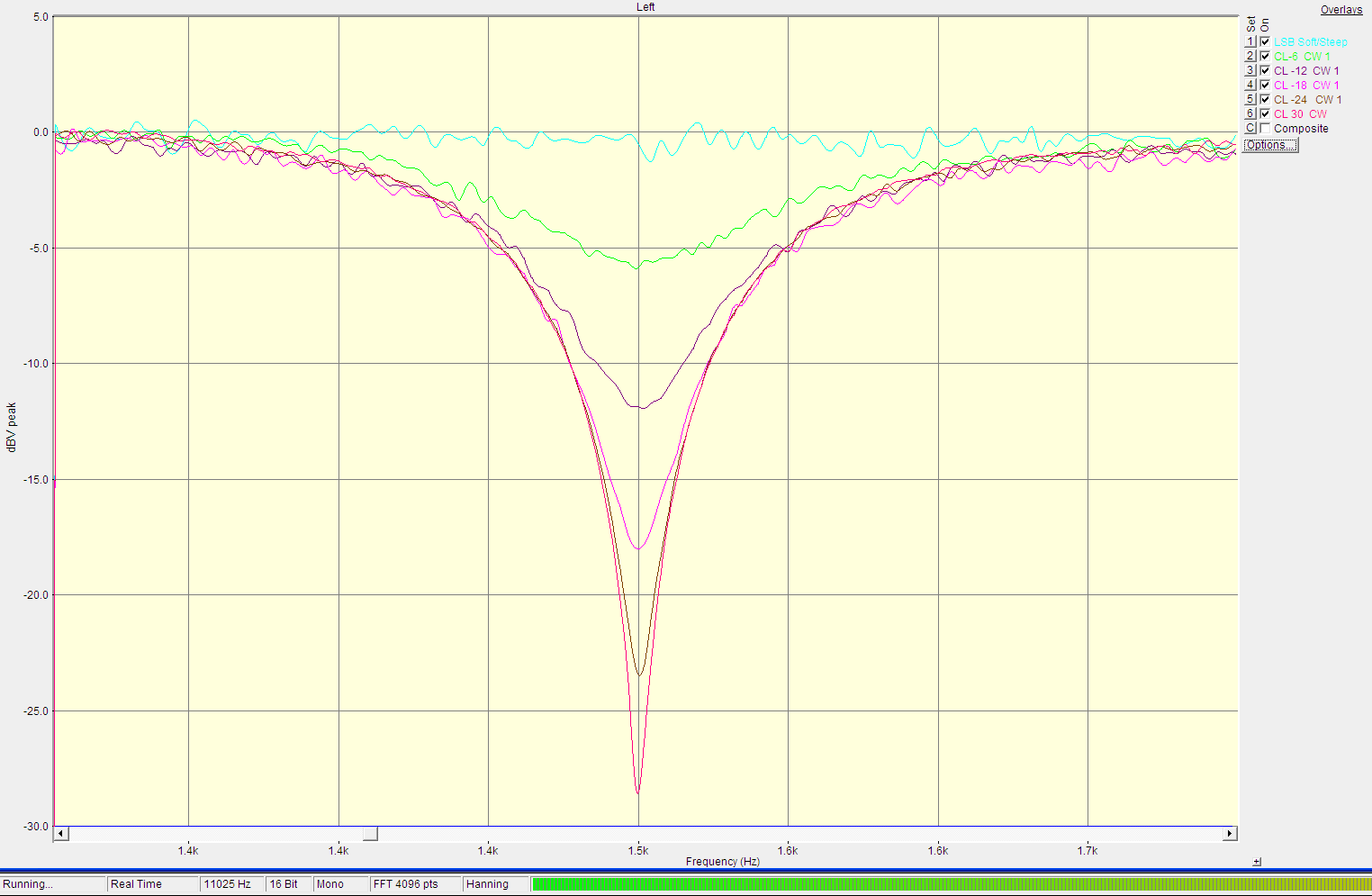
Yaesu describes this feature as an ability to put a user-adjustable amount of gain or null into the otherwise square-shaped passband of the DSP filter. See diagram on the right from the Yaesu operation manual. This is a pretty good description of the contour function as the testing proved. From the menu settings, we have two choices, LEVEL and WIDTH. Yaesu's operation manual comments are shown to the left. LEVEL is described in terms of dB. My measurements confirm this as accurate. WIDTH is described as Q-factor. Here, Q is not being used in the literal sense as one could calculate it from the graphs - but it's used in a more generic sense. Lower width settings, imply a higher Q, and that means a more narrower filter characteristic. Contour TestingContour can be either a null or a boost. We consider the null case first. In the plot below, contour width is set a 1. And level adjusted from 0 to -30 dB. Frequency range is 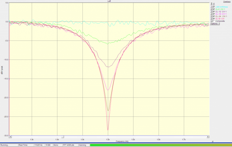
The actual rig filter plot is very smooth - the variations in the plot you see here are related to the speed at which I swept the curve and these wiggles in the plot don't exist in the filter. In the graph below, level is fixed at -30 dB, and width is adjusted over the range of 1-11. Notice the slight tilt down on the right side of the graph: 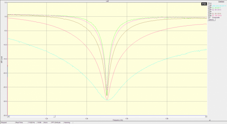
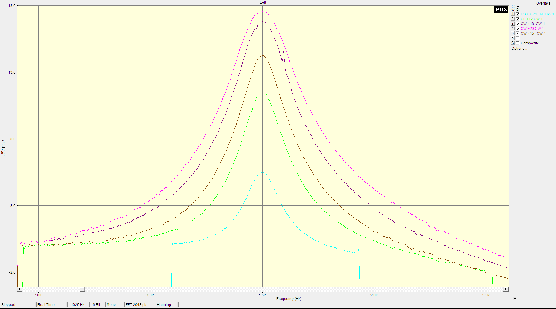
Considering the peak case, here the contour width is set at 1, and level is variable. 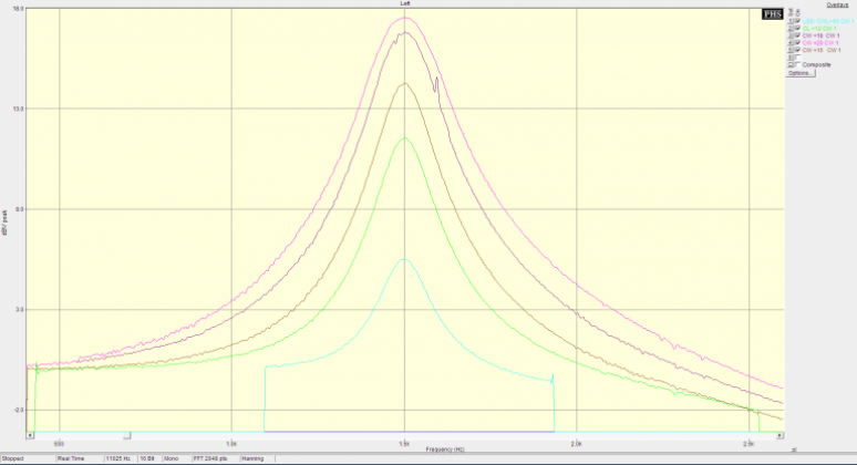
The rig's output remains clean up to the +15 dB point (below, LEFT). However, at +16 and above, the onset of clipping is observed. Notice in the graph above the +20 point does not peak with the expected +5db level over the +15 setting due to compression clipping at some point in the AF/DSP chain. From this, we can see that using the contour in the peak mode, levels of +15 dB and less are needed to avoid distortion products unless the signal is low enough to be below the AGC action threshold. 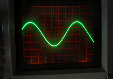 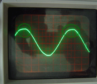
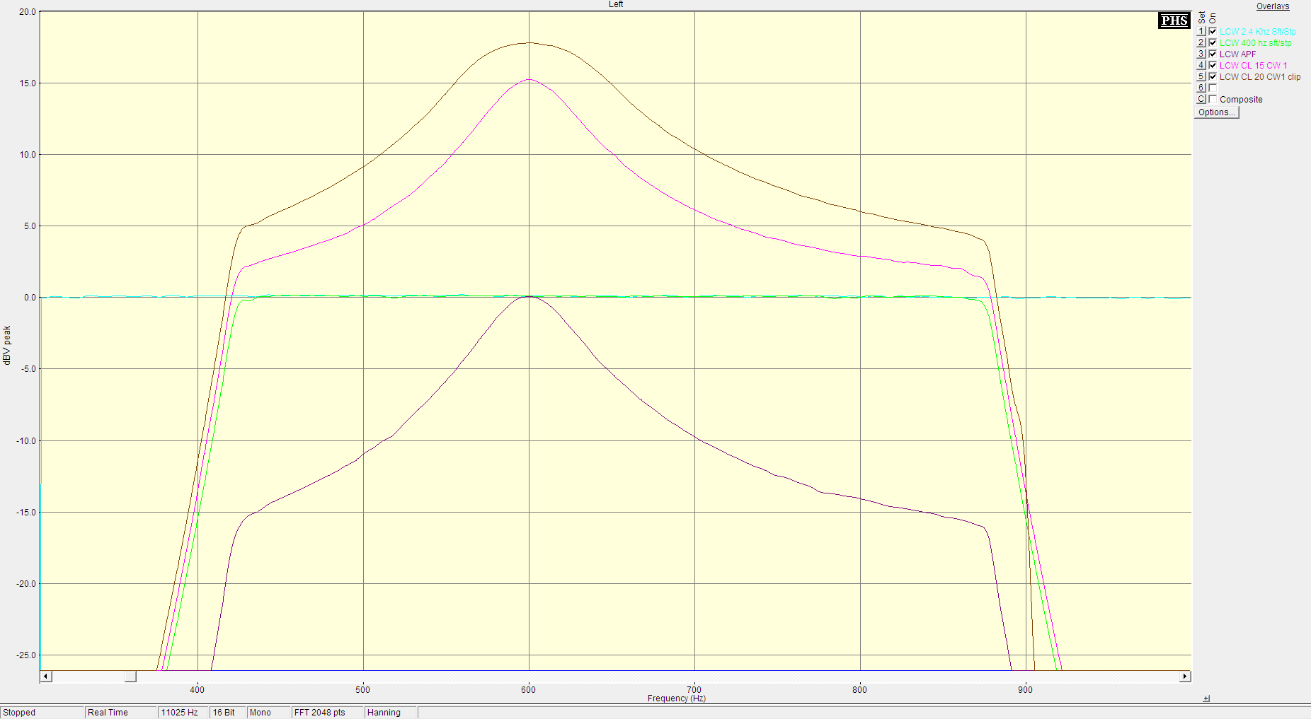
The Contour and APF LinkLooking at the plot of the contour control, and comparing them to the APF plot yields the relationship between the two. Here we see the APF plot (lower trace), a level=+15/width=1 and a level=+20/width=1 comparison. 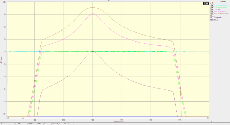
Next, we offset on the graph, the +20 trace, by subtracting 20db on the plot. Here we can see a perfect alignment of the APF plot (brown color) and the level=+20 db/width=1 contour line. The rounding seen in the center is the result of the compression clipping mentioned earlier. 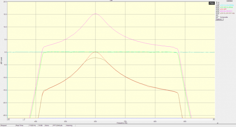
From this, we can conclude that the APF is actually a specialized case of the contour setting with these conditions: - Width = 1
- Level = +20 dB
- Offset = -20 dB
Finally, we consider the effect of the contour width in comparison to the APF. Here we consider a 400 Hz LSB CW mode filter with soft/steep form factors. Below the APF trace is represented by the bottom, most steep shape case. The green line is with the APF disabled showing the square top DSP filter shape. The contour widths are altered - and to allow for a matching of the various shapes, I have shifted each of the plots down so their peak values line up. Of course, the rig would provide the significant boost and the shapes would not line up in this way. But this organization allows you to consider the effect of other settings - as an alternative to the APF if you were to find the +20 effective setting of the APF too narrow for your preference. 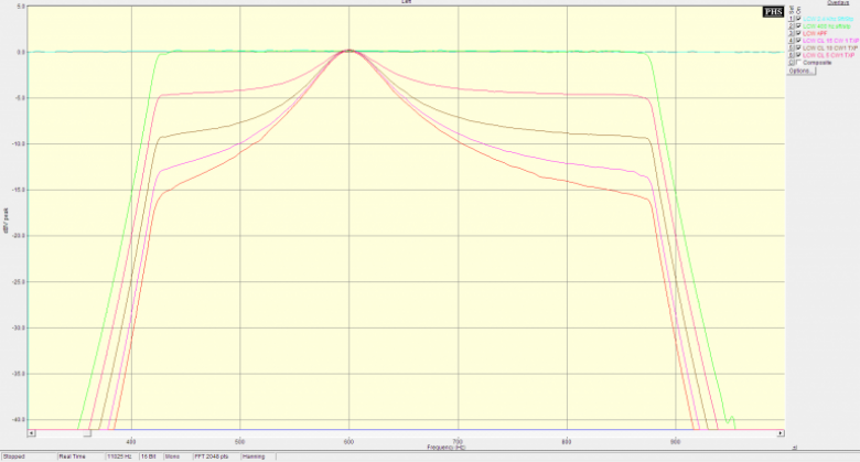
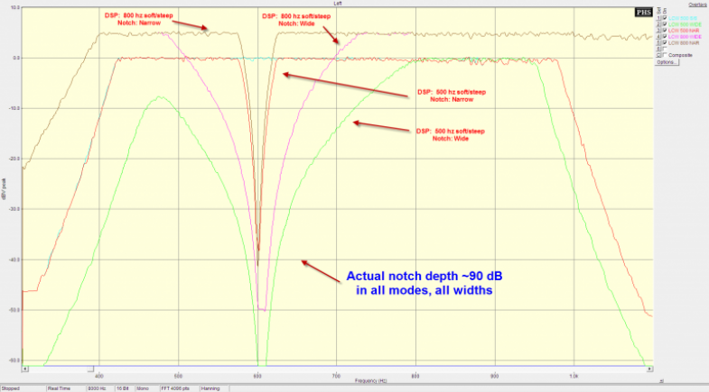
Notch Filter PerformanceThe notch filter has two modes - WIDE and NARROW. No technical details are provided by Yaesu beyond this description. To understand the width of the filter in actual use, consider this graph below. Testing was done with a S9+30 signal with 500 Hz and 800 Hz DSP modes. Soft/Steep menu settings. While testing was done in the CWL position, the notch widths applied are the same in all modes (confirmed in SSB, RTTY and PKT). Spot frequency was 600 Hz. Observations: - Narrow mode width: -3db points were 565 Hz and 635 Hz - for a effective width of 70 Hz.
- Wide mode width: -3db points were roughly 480 Hz and 730 Hz - for an effective width of about 250 Hz.
- Ultimate depth: the dynamic range limit of the DSP is around 90 dB. The notch filter provides ultimate rejection of 90 dB. Really amazing performance. [The rounding seen in the graphs is a result of local noise spikes detected by the sound card due to noise on the bench. This causes the noise floor on the plot to be raised.]
- The automatic DNR function was not tested.
- The indicated notch frequency has little correlation to the actual notch frequency - see comment below.
- The wide-mode notch setting is not suitable for CW operation - notice the left side of the graph in the 500 Hz mode - there is some interaction between the notch if the width is less than 800 Hz. Unfortunately, Yaesu does not offer DSP width settings in CW between 500 and 800 Hz
- There is an argument to be made that the peak attenuation shape of the notch may not be optimal - because all signals will have a finite bandwidth. That depends on the width of the signal you want to notch out and the sideband energy, if any. In the common use, for hetrodynes (fixed signals), the notch is perfect. And for CW signals, it's generally fine as long as the keyed signal has little click energy creating wide sidebands. I believe the notch filter, as currently implemented, is a good pick for both shape and width. Of course, if there were user adjust-ability options at a more granular level (shape and width), that would be even better!
The notch filter works great. Notch Filter Frequency Indication vs. 600 Hz Spot FrequencyThere is little correlation between the notch frequency actual center point and the indicated value. Perhaps this is a new math known only to advanced thinkers at Yaesu. Ha ha. But here in Kansas, USA, it does not make much sense. Perhaps I am overlooking some setting or other logical reason. For a 600 Hz centered notch frequency, the notch filter knob needs to be adjusted to these indicated frequencies: Mode | DSP Bandwidth | Notch Setting | LSB | All | 640 Hz | PKT LSB | All | 1500 Hz | RTTY LSB | All | 1540 Hz | CWL | 100 Hz | 1500 Hz | CWL | 200 Hz | 1500 Hz | CWL | 300 Hz | 1500 Hz | CWL | 400 Hz | 1500 Hz | CWL | 500 Hz | 1400 Hz | CWL | 800 Hz | 1300 Hz | CWL | 1200 Hz | 1100 Hz | CWL | 1400 Hz | 1000 Hz | CWL | 2000 Hz | 700 Hz |
While many of the DSP performance attributes may be called "software design decisions," I believe the frequency indication likely falls into the "bug" category. I will need to look at other firmware versions to see if this is a common theme or specific to this version of the FW. For the Yaesu Firmware Wish List... I would add two more items: - Have the frequency indicated when adjusting the notch frequency reflect the actual center point.
- Provide additional DSP width settings in the CW mode - I would love to see 50 Hz increments between 100 Hz and 500 Hz bandwidth settings, and then 100 Hz from 600 Hz to 1000 Hz. Something like that.
Conclusion The mystery of the APF is to be found in Yaesu's good observation that operators liked the contour control in the CW position. But that the level was too high to avoid clipping at the maximum settings and getting the center frequency set properly was problematic. The current implementation of the APF solves these problems very well. And in reference to my wish-list on the APF gain option - from this last graph series we can also conclude that moderate levels of user adjustable gain, with the APF enabled, of +15 dB or less, would allow undistorted operation. The notch works great, although the frequency indication is not useful. Future WorkThese test results pose some interesting questions. Some of which, like the relationship between the passband width and the signal strength, would require Yaesu comment and generally Yaesu does not explain their logic in this or that implementation choice. Others, like understanding the stage where the clipping occurs, may lead to hardware mods that could improve the rig's general usability. I am especially interested in the signal quality difference between what is available at the AF OUT jack (very clean) and the headphone/speaker jacks (some cross talk between main/sub and very noticeable hiss levels at lower volumes). And of course, there is the sub RX to consider. What's the filter performance in that receiver. And what can be done about the hiss levels with the CW narrow filter engaged. The FT-2000 is a wonderful rig with a lot of potential for fine-tuning mods. And the first steps to making the best mod choices is getting to understand the rigs baseline performance. I hope these plots are of value to the ham community. 73/jeff/ac0c |