Seeking Stability in a World of Excessive Drift The ProblemFor owners of the FT-2000 and FT-950 rigs wanting to fit an SDR, the highest performing solution is to match up the LP-PAN SDR with a good sound card. The RFSPACE IF-2000 mixer converts the rig-supplied "scope" output of 69.45 MHz and converts this to a 10.55 MHz output that drives the LP-PAN. The IF-2000 board sits in a space occupied by the DMU-2000 signal board and provides a very nice reversible mod. In my normal contest operation mode where spots are allowed, I run CW-SKIMMER fed by the LP-PAN tied to the LP-PAN bandscope to provide a local spot source. The spots are fed into N1MM. This is a great system because 100% of the spots given are workable stations. K3LR and W3LPL spots are the best - but I am more interested in what my antennas here are hearing. The IF-2000 + LP-PAN + CW-SKIMMER combo provides that. 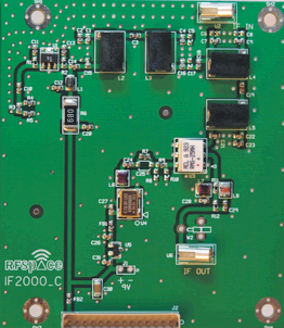
Unfortunately, the IF-2000 board has one weakness - the LO is very acceptable to drift. A 5C (9F) temperature change can cause the indicated signal to move around 100+ hz. This is generally not a problem for SSB users. However, PSK, RTTY and CW guys will find the convenience of click-tune a bit hampered by the subsequent tuning touch-up. And in our contest mode home-grown-spot source, it's a much more significant problem because I often run tight filters and there are many signals on the band. The 100+ hz of variation is one of the things that tends to drive an otherwise sane man crazy! What causes the temperature change? The FT-2000/950 chassis serves as a very good conductor of heat and when the rig is used for transmitting, the internal temp rises a bit. The heat from the finals is conducted through the rig and that causes the chassis to warm up. The IF-2000 board is mounted onto the chassis and secured in place by 4 screws. The heat flows from the chassis to the IF-2000 board through the conduction and radiation. The heat rise is pretty minimal, but the board is very sensitive to the changes. Savvy readers will observe the LP-PAN's oscillator will move around a bit as well. That is correct. However, the LP-PAN is not tightly linked to the rig's heat cycles - it's more dependent on the room temp variations. And here we would expect to see about a 2 Hz per degree C (or 1 Hz per degree F) change as the room temp moves. The LP-PAN's drift is less than 10% of the total system's drift and for that reason, it's stability is considered adequate by comparison. Easy SolutionsUnder the heading "Things that make you wonder why..." RFSPACE built the board I have with a +/-50 PPM oscillator specification. CTS offers a +/- 20 PPM version of the same part. The cost adder of this tighter spec part would be minimal - and that would significantly cut down on the drift due to the board. This issue has been brought to RFSPACE's attention by many individuals and as far as I know, the board is still being built with the lower spec part. Of course, other makers of these canned oscillator modules offer competing products. For reference, the CTS data sheet may be found here: http://www.ctscorp.com/components/Datasheets/008-0256-0_F.pdf I could not find any low-cost 80 MHz TCXO or OCXO modules. If these were available, that would be a very FB alternative as well... Breaking the heat transfer path I did not try this - but I think it would provide improvement. Replace the metal screws with a combination of nylon screws and add nylon spacers. The board would not have a direct ground via the screws, however, the ground provided by the H-labeled coax scope signal input should be adequate. DC ground is also provided via the board's header connection. A further improvement should be had by placing some insulating material between the board and the rig's chassis. Styrofoam or similar cut to the proper size would help to insulate the rig's heat gyrations from this board. Oven-Controller for our CTS OscillatorThe oscillator swap would help but not solve this problem. And insulating the board's thermal pathways would help but in my estimation not eliminate the problem fully either. What would is to add a thermal control feedback system to the board. That's why I found the web site of Jim W6PQL very interesting. Jim's very interested in old transverters for UHF work and has cooked up some very nice solutions to bring those oscillators under control by using small oven controllers. In this case, the "oven" is resistive heat. And the controller is a simple op-amp feedback system where the crystal's temp is sensed with a thermistor mounted near the crystal. My first plan was to use this kit: http://www.w6pql.com/crystal_oven_controller.htm And find a way to mount that controller against the IF-2000 board. Something like this: 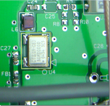
The oscillator is shown here in the yellow box. 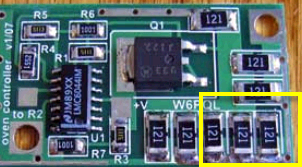
Jim's controller board uses these resistors to warm up the crystal 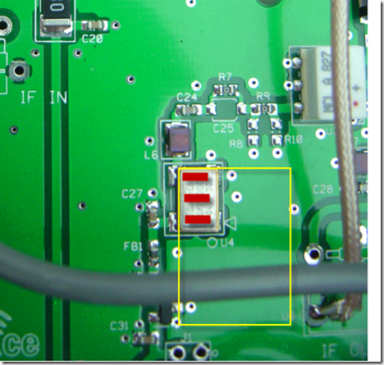
And I think the board could be positioned so that 3 resistors could be put into contact with the oscillator in an orientation something like this. The challenge of this installation is to thermally bond the resistors to the top of the CTS oscillator. The bond needs to be done through an electrical insulator because only one of the resistor ends is grounded. The thermistor could be soldered just to the right of the CTS oscillator. In the end, I could not think of a good way to ensure the board could be made to stay in contact with the crystal. Guys with more mechanical skill and a better night of sleep would probably find a good way to make this work - as it's a very simple implementation. However, in the end, I decided to try another of Jim's kits - the OCXO combination board. The Ultimate Solution - An Oven Controlled Crystal Oscillator for the IF-2000The kit I used for this project is found here: http://www.w6pql.com/vhf_ocxo.htm Jim has arranged the oven controller circuitry on one side of the board. And laid out the a buffered Butler oscillator on the other side of the board. The crystal can be soldered into a gap in the boards end simplifying the mechanical construction aspects greatly. 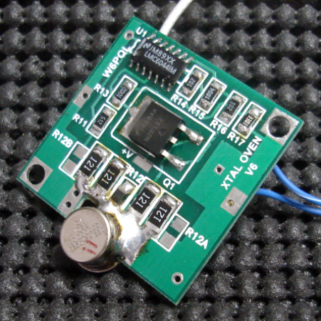
Oven Controller Side The crystal used was supplied by ICM. The turning point, as recommended by Jim, is set at 50C. ICM is the go-to company for anything crystal. The 4 resistors marked 121 are the heating elements of the oven controller. The smaller chip in the center of these 4 is the thermistor. I soldered the case of the crystal to the slot ground to ensure a very good thermal contact. In the final installation, the left-most 121-marked resistor was removed. This reduces the heat production of the unit but it also has a direct reduction in the amount of current the unit draws. With just the 3 121-marked resistors in place, the module draws about 180 mA. 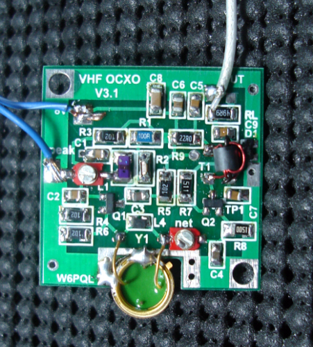
Oscillator Side Most of the parts in the kit are on the oscillator side shown here. Adjustments are provided to trim the oscillator frequency as well as adjusting output. The oscillator is intended for VHF/UHF applications and in this case, the oscillator ran at 112 MHz with the default components. Jim recommended adding a 33 pF cap in parallel with L1 and that worked great. The oscillator ran at 80 MHz right away. A couple of other component adjustments were needed to increase the output (the MC mixer on the IF-2000 is rated with a +13 dbm LO drive...). The changes were: R2 - Replace 330 ohm with 1000 ohm R8 - Replace 150 ohm with 120 ohm D1 - remove (serves a clamping function) 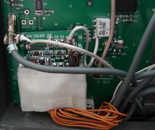
Mounting the OCXO onto the IF-2000 While the oscillator worked, I was unsure if the IF-2000 would play properly with the new OCXO. So mounting followed a quick-and-dirty thought process... Power and IF-2000 modifications are detailed later on the page (below). For thermal insulation, I just wrapped a few layers of 3M fiberglass tape around the lower end of the board. This provides enough insulation that the resistors are able to heat the crystal enough to regulate the temperature. And for a physical mount, I soldered one corner of the OCXO to the "H" connector (that's the coax feed line from the rig's scope buffer circuit). OCXO Power Source 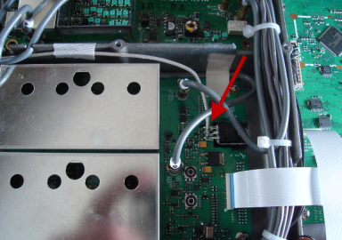
The OCXO requires an 8V regulated supply and the LO board of the FT-2000 provides that without trouble. IF-2000 Board Prep After getting the OCXO built and tested, it's time to fit it onto the IF-2000 board. Here there are 3 items to attend too: 1. Remove FB1 - this removes power from the CTS oscillator 2. Remove R9 - this disconnects the CTS oscillator output from the mixer input 3. The output of the OCXO is fed to the mixer's input (the white component, with the red arrow pointing to the input). Remember, this is 80 MHz VHF land, so keep leads short. I soldered my center conductor of the mini-coax to the mixer input, and tacked the coax ground to one of the unused solder points below R9. 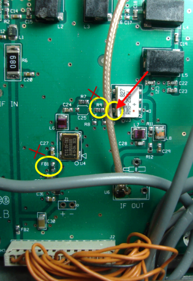
ResultsThe frequency is steady! I need to run the oscillator through a few contests to know but this year's Field Day playing will be much more fun now that the spotted frequency is reliable! Total project cost is around $65. And it was fun to build. I want to thank ICM especially for their help on this project and for making the excellent crystals. And to Jim W6PQL for cooking up quite a fine set of kits. This project really has me thinking about frequency stability and all the other applications where a OCXO could be put to good use in my shack and on the bench... |