Adding THE classic Yaesu HF rig to the hybrid lineup 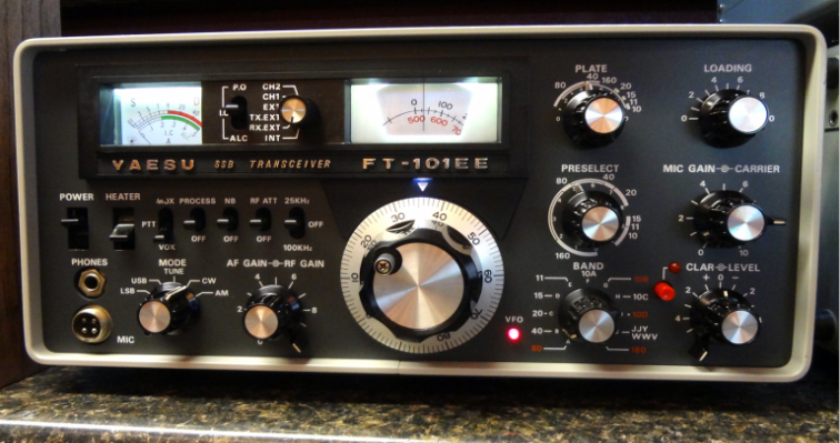
I've been looking at FT-101 models that had come up for sale and they tended to come in two types - very well used and pretty rough types that were cheap, and nice looking units that were selling for $500 or more in cases. Given the very high cost of a set of final tubes (about $180 from RF parts at the time of writing), I did not want to make a big investment in the rig. Additionally this rig was a favorite of many CB enthusiasts back in the day and in that role many power boosting or other modifications were popular. A local auction had this rig, the remote VFO and speaker/patch listed as a set. Functional condition was "working RX, no transmit." The cosmetic condition was good. I placed a reasonable offer for it and as luck would have it, picked up the trio as the auction winner. The radio sat on the counter with an occasional listen to the RX until the winter. Over a holiday break I decided to pull it over to the bench for a checkout and the sequence of events below followed. Initial Check OutCosmetically the rig was clean on the face with just a few scratches on a couple of knobs and some worn lettering above the MOX switch. Internally the rig was clean as well. Examination of the finals and associated circuitry showed no burned or overheated parts - a GREAT bit of news. And the 3 tubes were all NEC brand - another great sign of gentle care. Most mistreated rigs had finals swapped regularly and the US brands eventually replaced the Japanese brands. The Transmitter SurpriseAll of these old rigs suffer from buildup of "crud" on the many wafer switches. So the first order of business in a checkout for function is to clean these with Deoxit. You have to be careful with the stuff though because it can soak into the switch insulating material and cause more problems. I try to use the green label Deoxit fader lube which is less aggressive than the normal Deoxit red label stuff. So it was not a complete surprise to see the transmitter kick into action after some switch cleaning. After some investigation it was nice to see the rig making full power on the low bands! Recapping a Couple of BoardsTwo boards were recapped in full. The regulator board and the AF board. The regulator board provides most of the key voltages and some regulation for rig circuits and shorted caps are bad news for expensive and hard to replace stuff like transformers. The AF board was recapped primarily due to the large number of caps showing cracking and for which I assumed were ripe for leakage 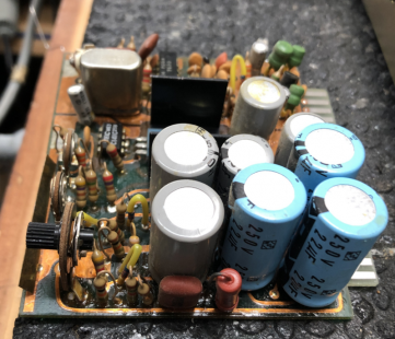 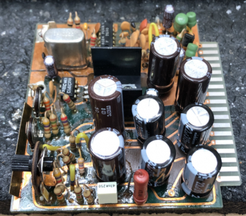
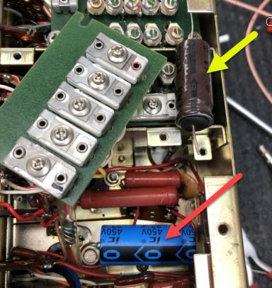
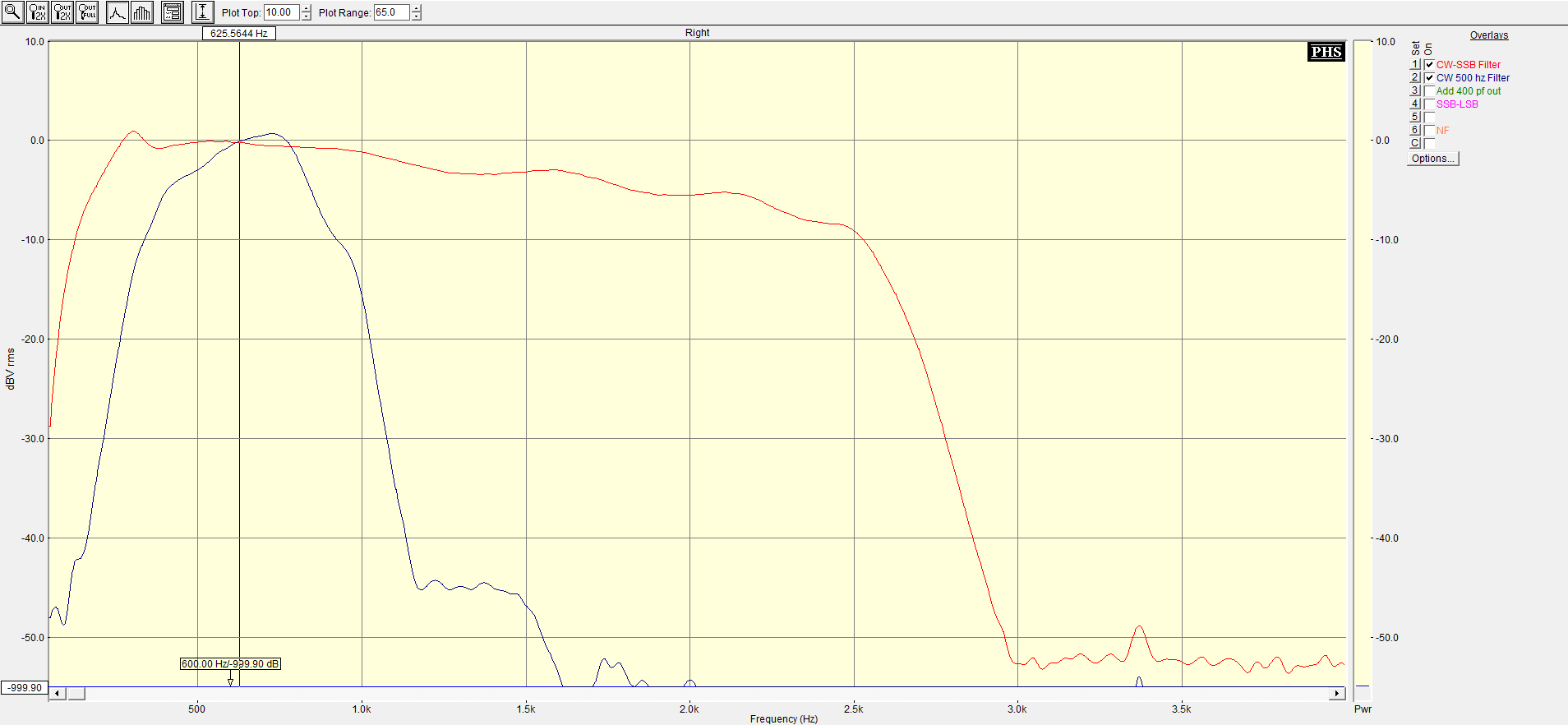
One of the HV caps tested as leaking a bit but I replaced both for the same reason - transformer damage paranoia. A few other caps in the rig were replaced as well. Some preventative, and some based on apparent need... First was the screen cap filtering cap - the original one shown left (yellow arrow) was bulging and discolored. The original placement had the cap placed adjacent a power resistor and I suspect it had baked the cap over the years of use. The blue replacement is shown mounted (red arrow). A couple of other caps were replaced based on comments I found on the web. These caps are associated with some pretty big messes when they fail and were easy to replace - once found! Failures seem to be due to being a bit underspec from a voltage standpoint rather than leakage or value drift. Both are tucked down and near the chassis and take some hunting to find. C13 - the 80-10 padder cap (mica) C131 - the 160m padder cap (mica) Alignment CommentsAfter tweaking the RX trimmers and finding a marked improvement in sensitivity, a complete alignment of the rig was performed. I was surprised at the improvement as alignments on the Kenwoods that I have worked on previously did not benefit much from alignment in general. Murphy was in the shack at the time though with three of the small padder caps breaking and had to be replaced. At that point all the other trimmers were tested for rotation before continuing. Replacement padders were surface mounted over the padder cap locations after removal; the replacements were pulled from a parts rig. The rest of the alignment was unremarkable. A cold neutralization of the finals was performed - I recommend this method because the normal method requires quite a lot of key-down time on the very expensive to replace sweep tube finals. A Couple of TweaksThe primary use of the rig will be for rag chewing and to that end a couple of other tweaks were made to enhance the armchair-copy and creature comfort. The VOX delay (used for CW break in as well) was too short so the delay cap value was doubled to increase the max delay length. There is only one AGC time constant on the rig. As most guys worked when rag chewing are good copy, I prefer a longer hang time so the AGC timing cap was doubled as well. A CW filter was pulled from a parts rig and installed into the open slot on the rig. The Yaesu filter is a crystal type, 600 Hz with 6 poles. Finally, I generally don't like the incandescent lighting which has a yellow cast. The effect with the color scheme on the Yaesu looks better than on the Kenwoods but I prefer white LEDs. Refitting LED onto the FT-101 is pretty easy - the stock lights are fed by AC and will have a slight but noticeable flutter if fed directly. A diode + cap provides stable DC for the LED strips tacked into place with hot glue. A series resistor between the supply and LED allow for brightness adjustment. Tuning for CWThe stock carrier frequency settings result in an 800 Hz CW center frequency. The rig uses USB for the CW receive mode setting and if one is willing to compromise USB SSB frequency response, the CW frequency can be moved to something different - my choice favors 600 Hz. Once the CW filter response is centered as you like, the CW carrier frequency is adjusted to give the 600 Hz matching offset. Shown here is a system response plot (AGC disabled) with the center frequency at about 625 Hz. Click on the plot for a higher resolution view. 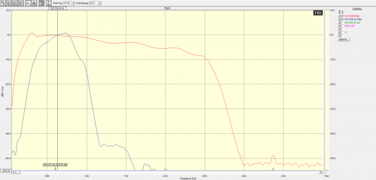
2-Tone IMD and MDS TestingMDS & IMDDR3 (2 Khz) were checked with the stock -40 FET in the first IF amp location, and then with the -211 "improved" replacement. I did not measure an improvement in MDS (-127 dBm on 40m w/CW filter) with the -211 compared to the -40, but the DR3 did improve from 66 dB to 68-69 dB with the -211. 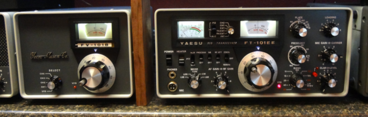
FT-101F in FT-101EE Clothing?In a final bit of additional good news, I noticed on a comparison table that the very rare FT-101F and some of the latest vintage FT-101E had identical internal board complements. In looking at the numbers of the boards in the rig as well as a few other tell-tale signs it looks like the FT-101EE here is one of those rigs. |