Taking a quick look at one of Jack's latest filters 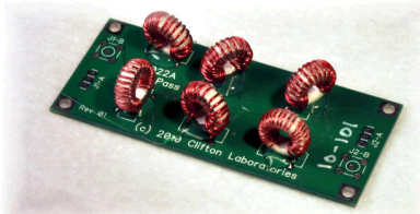 I spend a lot of time looking at filters here. I spend a lot of time looking at filters here.
The AC0C FT-2000 roofing filter by Network Sciences is the one probably best known to visitors of the site, but I love filters of all flavors. Active, passive, crystal, and even DSP. Another example of that obsession is found in the Ultimate Audio Filter detailed elsewhere on the site- complete and total overkill for the purpose - but as a "filter-nut" - it's my kind of project. While I don't have a local BC interference issue at this QTH, it was logical to get one of Jack Smith K8ZOA's HPF filters and put it to the test. If for no other reason than to see "how the professionals do it." There's another reason I wanted to look at the filter. In discussing the various filtering options available to FT-2000 and other rig owners, there is a bit of confusion as to the proper filter type for a given interference source. I have recommended hams consider Jack's filters for the BC suppression type of interference in the past - just based on Jack's advertised performance and his sterling reputation. But I had not been able to speak from actual bench experience as to the actual performance one can expect. Jack is pretty well known in the test and instrumentation circles as well as for producing an exceptional line of ham related products from basic filters and buffer amps, to Jack's latest big project - an active antenna. The great thing in buying Jack's stuff is that you know you are getting his test bench as part of the project. And I expected even before testing that the test results on my "rookie" level bench would match up to Jack's advertised performance without a doubt. I was not disappointed. This filter hammers the BC band just as he advertises... You can find more information about the filter on Jack's web site by clicking HERE. Z10022A HPF 9-pole Filter 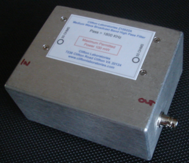
The filter is available in a variety of finish levels including box, waterproof levels and connector choices. I planned to use the filter indoors so I selected the basic case option and BNC terminations. The filter was delivered about a week after order - shipped by USPS Priority Mail. With Chebyshev filters, the roll-off is very sharp and the passband flat, but there is significant group delay delta across the passband. Contrast this to the other common use of Chebyshev filters - narrow band crystal filters. Chebyshev designs have nice tall skirts and a good shape factor. However, here the group delay is a big problem and manifests as ringing characteristics. For a filter in this receiver protection application, the group delay is not a consideration because the "passband" is huge relative to receiver passband. 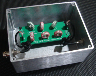
Internally, the box has a large amount of unused space. But that's an asset when dealing with high stopband levels - packing the circuit into a compact enclosure will likely create a compromise in the stopband performance. Note the coax is further decoupled with ferrites on each side. And the BNC jacks are shielded on the internal side to minimize the impedance "bump" of the connector as well as to optimize the isolation - micro level details come into play at the attenuation levels Jack's deliverying. I know from prior personal experience, to obtain the performance levels the design is capable of, the coil build must be exact. Orientation is a factor as well at these levels. Inductance levels must be trimmed to accuracy levels of under 1% and that hides the complexity of the board - it looks more simple than it is because the in-circuit value and tested values can easily have this amount of error. The only way around this is to correlate the performance and the tested values and offset accordingly. I'm uncertain what Jack's construction method is exactly - but little things like this are most certainly part of the "recipe." Advertised specifications pulled from Jack's web site are: - Filter Type: 9th order 1 dB Chebyshev.
- Input and Output Impedance: 50 ohms
- Cutoff Frequency: 1.8 MHz
- Loss at Cutoff Frequency: Typical 1.6 dB
- Ultimate Rejection: > 90 dB, typically > 100 db
- Input VSWR: Less than 3:1 1.8-30 MHz.
Z10022A Advertised Typical Performance Plot Analysis The objectives of the bench evaluation were to confirm the rejection claims made on Jack's web page. Looking at this plot for the 1.8 MHz loss of this plot pulled from Jack's site, the 1.6 db number is found on plot tick A (highlighted in yellow). Stopband attenuation is at the floor of Jack's plot indicating >100 db levels. 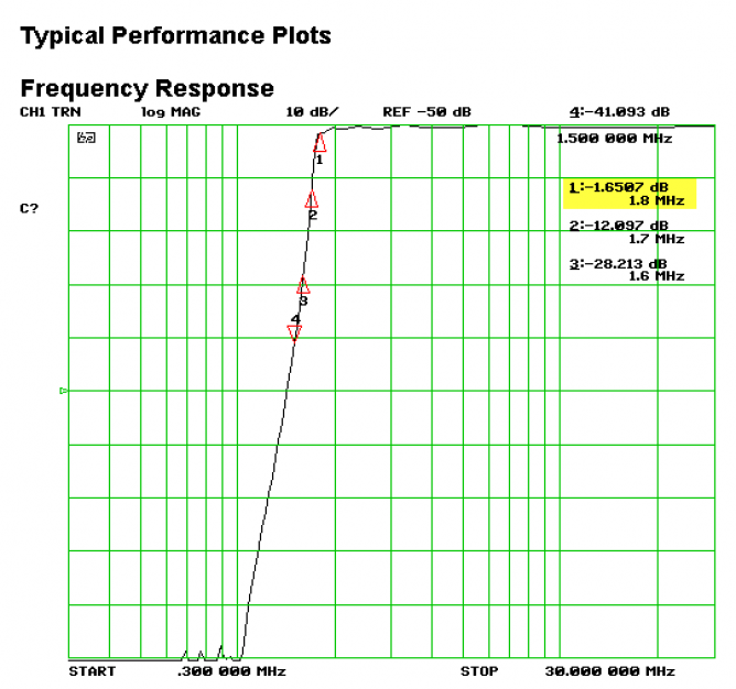 A 1 db Chebyshev design should have around 1 db of ripple in the passband. And on this chart from Jack's site we can get a feel for the ripple in the passband – around 0.75 db by “eyeball” interpolation… Data point #4 from the graph is at 0.6 db - within the 1 db designs expected range. 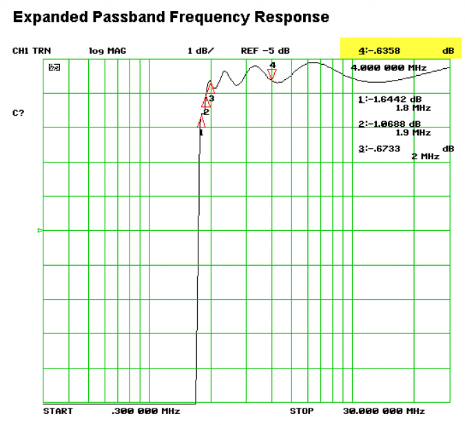 The last metric of interest on our tests today were input match. Here we can see SWR on Jack's data at 2:1 across the passband with a bit of a peak at 1845 KHz… Note that SWR match is really a "critical" metric from a receiver standpoint - in that very slight loss due to SWR is generally negligible. However, small variations in component values from the ideal can radically alter the SWR. And so we can get another quick check of the sample in hand vs. the web site data by comparing the input SWR plots to what we would measure later on the bench. 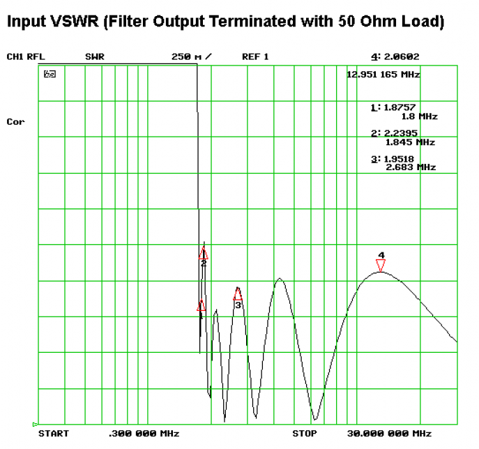 Z10022A on the AC0C Bench The test setup on the AC0C bench is composed of an N2PK version 4 VNA, RG400 double-shielded coax and BNC terminations. A calibration run was made prior to the test. Metric: Loss at cutoff. Specification: -1.6db typical Data: Actual measured loss at cutoff –1.6db @ 1.8 MHz (red marker #1). Result: Match Metric: Passband ripple. Specification: 1 db typical (based on design) Data: Ripple levels - about 0.6 db in the passband from the cutoff frequency - all the way up past the 6m bandspace. [Jack does not show data beyond 30 MHz but I wanted to see what 6m looked like because today's typical HF rig covers 6m in most cases.] Result: Match Metric: SWR - 3:1 or less - (check for approximate match between advertised and measured levels) Data: SWR under 2:1 at all points in the passband – and no sign of a peak around 1845…. Both measured values and the plot from Jack's site are a good match. Result: Match 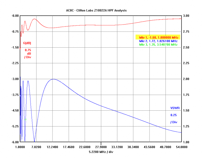 Metric: Stopband attenuation: > 90 db typical Data: >90 db. Reaching 110 db (essentially at the limit of the VNA noise floor) at some points. Result: Match 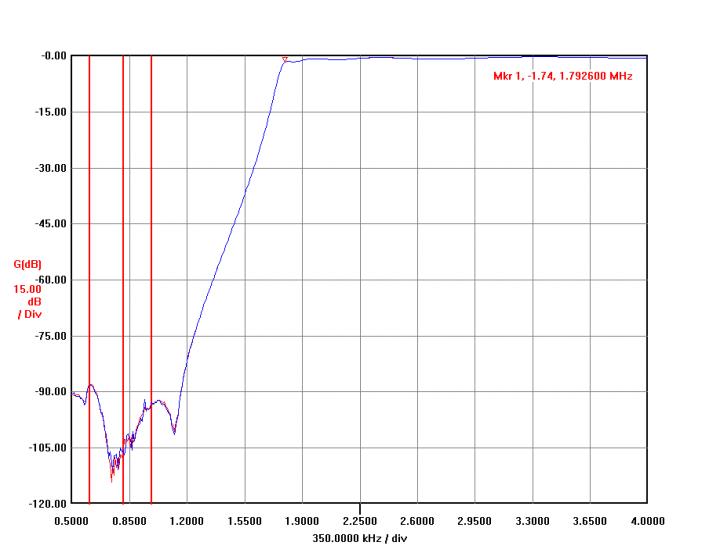 What about IMD? The only other metric that may be considered as interesting would probably be IMD. For example, a pair of very strong BC stations picked up the the feeding antenna into the filter - that should generate some level of IMD products which could be detected in the passband. However, I don't believe this to be a significant omission or issue of worry for a few reasons. Strong signal IMD testing is extremely difficult to perform because at the levels these passive components would start to produce DETECTABLE levels of passive IMD is already in the approximately 0 dbm range or much higher (this is primarily a function of core saturation, in this example). Having very strong signals is not enough. They need to be spaced perfectly. In fact, the IMD product needs to be located near the signal of interest in your ham band - within a few KHz. That's a combination of events that is just too extreme to be considered a real issue. In a typical station, there are going to be dozens of spurs and birdies caused by sources inside the shack and neighborhood which are going to be far more likely to give you trouble than the ideal combination of IMD phantoms associated with this filter. In fact, If you have two BC stations that are that strong, IMD phantoms from this filter are going to be the very least of your worries. Overloading the front end to the point of possible damage is a more likely scenario! One other consideration: there is some comfort in considering that one of the few guys doing serious characterization of filter components at extreme signal levels is...Jack Smith. To get a feel for what Jack does in his spare time, you can take a look starting here, for example... http://www.cliftonlaboratories.com/ferrites,_inductors_and_transformers.htm So to my thinking - buying a filter designed to protect against strong signals from a guy who is doing work in the field is pretty logical. ConclusionsThe data support the rejection claims advertised with the filter. It clearly works as designed. If you have problems with a AM broadcast station giving you problems below 160m, the Z10022A will terminate those problems with extreme prejudice. In my configuration, I have the filter in the RX antenna input loop along with a splitter that feeds my skimmer server array. It is exceptionally cool to have the rig tuned to a BC station - and then enable the HPF filter - to see the BC station completely disappear from AF feed as well as from the attached bandscope. ---------------------------------------------------------------------------------------------------------------------------------------------------- I'm a cheer-leader for products that work as expected. Few products are perfect and without compromise. However, generally speaking, the stuff Jack makes is designed, tested and can be expected to work as advertised. As I have noted in the Microham MKII comments elsewhere on the site, this attribute is too rare in our modern high-tech world. And when excellent performance is observed, it should be singled out as such. The Z10022A is such a product. |