 Me and Mrs. Jones... Me and Mrs. Jones...
ORIGINSIn one of the last contests, the band-switch in my beloved SB-200 amp arced putting a temporary hold on using that unit. It was long overdue for some tank work that I had been putting off. And there are several other things I needed to clean up on the amp anyway. All of this seemed like more work than I had time to do - especially with contest season heating up. The solution was to find another amp that could be used in the interim. The problem is, most guys with amps in otherwise good shape are not really happy when you tell them you want to borrow their amp so you can run RTTY contests with it. However, a friend of mine did have a few amps and an Alpha 76PA was one on the list he mentioned that we could work something out on. Following an initial check out of the amp, an arrangement was made and the old Alpha had a new home. I'm not sure why, but I new I loved that amp right away. It was perfect for my application - a strong table top amp that would fit into my existing bench, everything worked as it should (well, most everything...) and it even had a good reputation even among the RTTY contesting community. Around that time the old Billy Paul song "Me and Mrs. Jones" was on the radio and, as songs do, stuck in my head. Given the excellent feel this amp had, I knew we had "a thing going on." I got to calling this amp Mrs. Jones after that. For younger hams, click HERE to enjoy this classic. PROBLEM AREASThe amp was ready for war except for 4 problem areas of somewhat debatable severity. - The front panel had the Alpha soft-paint disease. Compounded by adhesive (band tune marking notes?) that would not come off.
- The amp was quiet, but it's open frame relay was pretty busy especially in contest CW work. And I like things quiet other than the radio.
- The incandescent light bulbs illuminating the meter worked but having been spoiled by the addition of white LED on the SB-200 project, these had to go in short order.
- The plate choke had been burned - something that happens when the amp is used on 12m - and a frequency where the plate choke is resonant
The only other area of concern was the relative scarcity of the 8874 tubes. Properly cared for, these tubes can last just about forever. However, absent proper grid protection, I worried inadvertent mistuning would some day catch up to me and give me a very bad day. So as a longer term project, I knew grid protection would be on the list of fixes. COSMETICS
Like any good contester, I tackled the cosmetics issue first - we can all agree that a handsome amp produces more powerful watts than an ugly amp. :) Fortunately, the fixes here were pretty easy to implement. 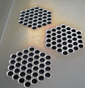
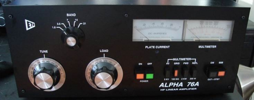
The clam-shell top case was painted matte-finish black to match the rest of the shack gear and to match the new faceplate. The case surface finish had only a couple of minor scratches to be fixed and no other surface prep was needed than light sanding and a soap/water wash. Taking a page from Matt KK5DR's very excellent publication on his work with the A76, I countersunk the internal side vents slightly . While I'm not sure how much actual difference it makes, the result looked very nice. Too bad it's just on the inside... Alpha sells replacement face plates and it's very easy to swap the old one for the new one... The new faceplate (below) is a matte-finish black color with white lettering. Unfortunately, the 10m position is not lettered. Another idea from Matt was to use black hex-head screws to replace the stock Philips screws. The difference it makes is really amazing. Thanks Matt. 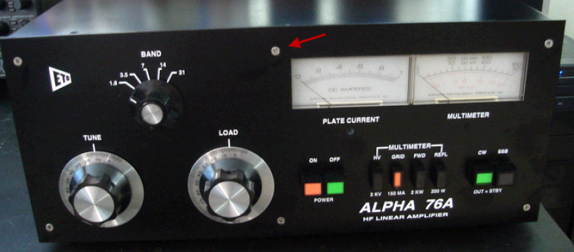
To replace the incandescent lights With LED required some thought. The space behind the meters includes the logic board for the amp's existing controls and additionally accommodates the HV rectification/filtering side. So being careful is important here... I eventually settled on building a plug-in board that mounts into the existing light sockets and serves to hold the LEDs. At this point, I had no idea what number of LEDs would be needed, and how to space them. This breadboard design would allow me to play around with that much more later. To provide a transmit indication, I added two sets of blue color LED which you can see in the picture below. [They appear faint in the picture due to the camera's handling of blue light but the light level is much stronger in actual view.] Overall, the result was very nice. 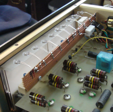
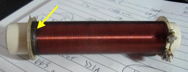
PLATE CHOKE AND A SOLDERING SURPRISEClose examination of the plate choke indicated some heat damage on the HV end. I had an Ameritron plate choke in the junk-box which was earmarked for the final SB-200 tank overhaul but it was pressed into service here instead. While the self-resonant point of the choke is indicated by Ameritron at 11.8 MHz, I put this on the VNA and did not like where the resonances seemed to be. Some experimentation with additional wraps both increased the coil's inductance further and pushed the resonances further away from ham band segments resulting in the choke seen below, right. 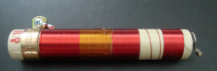
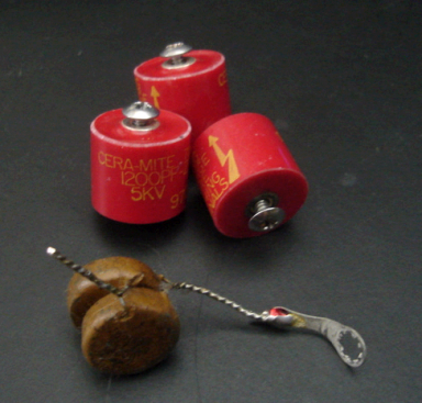
The plate blocking caps were replaced with some old doorknobs I had in the junk-box. Rated at 5KV and hi-pot tested to 7KV, they will work out fine. I'm not sure how this amp has done so well with the stock caps - but they look (and measured) just fine. I will feel better with the doorknobs in there in any event... While swapping the plate choke and coupling caps, I noticed a couple of the anode caps soldering connections were loose! They literally look as if the solder has evaporated. All 3 caps were re-soldered as a precaution. As the work progressed, some bands showed intermittent performance in some cases and after investigation, a couple more of these missing-solder-joint problems were found. 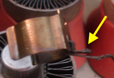
Eventually, all the solder joints in the tank were re-soldered because several more poor connections were found on the band-switch connections. I had never heard of this kind of an issue before and I really appreciate Carl KM1H for suggesting I look for it. I used the shield of some 219 which provided a flexible mounting arrangement for the doorknobs. I wanted something that would flex easily in the event additional work on these items would be needed later. Once the final work is complete on the amp, I may build up plated copper strips to replace the braid as it gives a cleaner and more finished look. 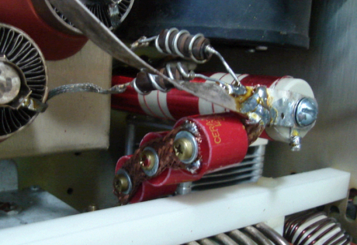
UNDER THE HOODHaving fixed the functional and cosmetics issues, the next project was to swap out the Collins-inspired RCA input jack with a more contemporary SO-239. And to put the fast and quiet mod on the relay. This relay mod part of the program comes in at zero on the beauty scale - and a 11 out of 10 on the silent scale… The original DPDT relay was the clunk-clunk variety. Quieter than the SB200, but still pretty loud, and slow, as things go. 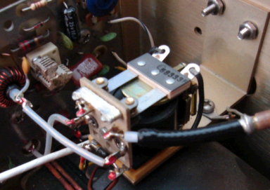
I saw an excellent installation on the Max-gain web site but it comes at the cost of two pretty expensive relays instead of a single unit, and provides no improvement in speed or sound over the use of the reed relay for the input side - originally recommended by Richard Measures. What I installed here is the same solution as implemented in the SB200 mod and that solution was well tested here in the shack over the last year! So the final solution was, a Panasonic RF reed relay on the input side - and a RJ1A clone from Gigavac handling the output duties. 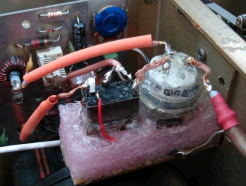
As mounted, the reed relay is essentially silent. The ceramic and metal case of the vac relay is an excellent sound conduction surface and while the relay is much quieter than the stock relay, it’s made a lot quieter with the application of a layer of the hot glue coating. The hot glue, when cooled, has a rubbery texture making it an excellent sound absorber. The solder wick braid prevents sound sound conduction from the relay to the chassis by the stiff wire conductors that were provided stock. The heat shrink tubing is fitted but not shrunk for the same reason. Interconnection was done with RG316. The reed is a 12V type so there is a 1K dropping resistor on the back side of the relay (under the white heat shrink). A clamp diode is fitted on the pins of the vac relay to kill the back EMF. Functionally this arrangement works fantastic. It's fast and quiet. But the pink closed cell foam used as the mounting base and sound damper just looks too odd... I will have to do something about that foam eventually. Swap it with some open cell black foam which would look much more professional. At this point only the grid protection board needs to be added for the final mods. GRID PROTECTION - PART 1Given the popularity of the amp, I thought others surely would have thought about this grid protection issue before and published a solution. And in hunting around on the web for ideas, I came across a circuit idea by K6XX. He's using an opto-iso across the Alpha's 10 ohm grid current sense resistor and using that to trigger a 555 once a certain threshold is reached. While I don't think the schematic is correct (the 555's trigger is tied to the fixed regulator output), it was a clean and elegant solution. Another consideration I had been kicking around was the idea of putting a idle position onto the blower motor. The blower is already pretty quiet in the amp, thanks to rubber mounting and a 25V buck winding on the transformer, but for an amp that's running RTTY contest duty part of the time, and idling along the rest of the time, there seemed an opportunity to do something in the variable speed realm. In addition, I would like to have the fan run until the amp had cooled down and as it's built, once the power switch is pushed, everything powers off immediately - cool or not. And I really needed to take a look a the QSK timing as well - that was something I had not measured and wanted to take the opportunity here to measure the performance of these relays. All of these ideas seemed to suggest a bit more circuitry than I wanted to hang together especially when a much better solution just seemed to be right at hand. GRID PROTECTION - PART 2Instead of implementing the various bits of control circuitry together in a discrete fashion, why not use a micro-controller to do the work? It was at that point that this grid protection project turned the corner and - some could argue - got completely out of hand... What was finally implemented provides these basic functions: - Real-time grid current measurement and display - with warning and lockout functions
- 3 mS QSK switching with rig transmit inhibit feedback
- Automatic control of fan speed based on tube and transformer temperatures
- 4x20 LCD display on a remotely mounted control head
- Real-time measurement of tube and transformer temperatures with peak-hold function to indicate the max temps reached
- Standby touch button (the stock standby solution requires careful pressing of the CW/SSB mode into a not-pressed mode)
- Morse code beeps via piezo sounder to provide audio clues for key events
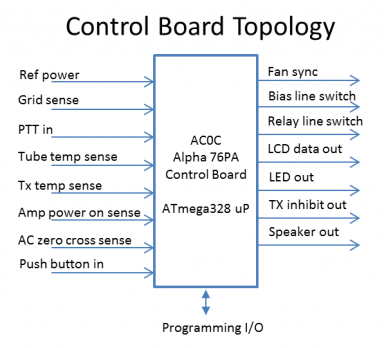
FUNCTIONAL DESCRIPTIONThe control board is built around an Atmel ATmega328 uP with a few interface parts to handle levels and provide filtering. GRID PROTECTION The opto-isolator sensor tied to the amp begins to detect grid currents at about 85 mA. While I typically run the amp with 50 mA or less of total grid current, this threshold is good because it allows for a warning to be issued via the yellow LED. A second threshold at about 150 mA will cause the amp to go off line until the PTT line drops - during this time, the yellow LED continues to flash and a Morse code G is sounded. After the PTT line drops, there is about a 1 second delay added to this to prevent repeated attempts to hammer the amp and avoids the need for a manual reset. The automatic-enabling is handy when tuning the amp. Detection speeds are in the mS range. The LCD display shows the current measured grid current, as well as the peak grid current measured in the last transmission cycle. FAN CONTROL The cooling for the amp is split between the stock internal blower, and an added muffin fan behind the transformer. The added muffin fan provides additional air flow around the power supply components and helps to pressurize the cabinet vs. the stock solution. External fan connects are provided for an additional fan built into the cabinet and is positioned just above the cabinet's exhaust ports preventing heat build up above the amp's top. 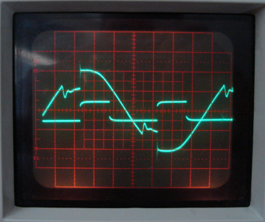
Fan speed is varied with a uP controlled triac/diac driver. This requires synchronization with the AC line waveform and another input samples the AC line providing zero cross information to the uP. Temperature sensors over the tube and transformer feed into the uP inputs where an ADC digitizes the readings of the thermistors. A calculation results in a temperature reading displayed on the LCD. The 3 thermistors over the tube exhausts are in parallel. Due to the nonlinear response of the thermistors, individual monitoring of each tube separately is not needed. In the event any one tube is running hot, the result causes that thermistor to show a much lower value which in turn triggers a much faster fan speed. Fan speed is set by a PWM system (trace at right shows PWM operation and the effect of cutting the AC waveform). The AC waveform is filtered to prevent switching transits from generating HF noise. The fan speed varies based on the temperature read, and is closed loop from that respect. Settings in the uP allow for easy customization of the speed curve, as well as setting trigger points for special amp behavior such as ensuring a minimum speed once the transformer reaches a "hot" setting (the transformer can take a few hours to cool down) - as well as turning the fans off if the amp's power has been turned off and the tube/transformer is determined to be cool enough. In the event tube or transformer thresholds are met, the amp's red LED is illuminated warning the operator of the amp's temperature status. And at yet higher thresholds, the control board can take the amp offline to prevent damage. The advantage of this configuration is that it's self-adjusting regardless of mode. In light-duty modes like SSB or CW DX chasing, the amp will be at idle most of the time. And for serious work like run-mode in an RTTY contest, the fan automatically steps up speed on all fans to ensure maximum cooling capability is active. The LCD display shows the current and peak temperatures measured in the last transmission cycle (for tubes) - as well as the current and peak temperatures for the last power on cycle of the amp (for the transformer). QSK The uP manages the QSK cycle in this sequence: From a PTT line pulled low detection: - TX inhibit set - prevents TX from giving the amp drive
- Relays set - DC switched to the relays - at the same time - amp bias is applied
- Delay 3.5 mS - gives relays time to settle fully
- TX inhibit unset - allow TX to deliver power
This sequence is duplicated at the time the PTT line is released. In this way, hot switching is prevented in all circumstances. In the case of a detected fault condition where the amp should be pulled offline, this similar sequence is executed preventing hot-switching even in the case of a fault. To assure instant response, the QSK cycle is managed by the uP under an interrupt driven cycle which is triggered by the buffered PTT line. The relays are driven from the 40V external supply and have series current limiting on each relay. This method is a combination of the work done by WD7S and Richard Measures - based on notes from their sites. No diode clamping is used as that tends to slow down the relay opening. And to avoid trouble with the back-EMF at relay opening, a 750V MOSFET switch powers the relays. The relay engage/release cycle measured at under 3mS in all circumstances - with the reed relay being much faster than the Gigavac vacuum unit, of course. An additional benefit of the PTT line buffering is the amp can be driven by any solid state output. The original Alpha design had the grid trigger flowing through the PTT line. QSK measured timings below. About 2 mS on close, and about 3 mS on open. 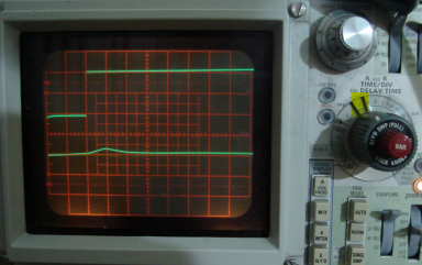 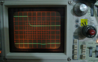 SWR The amp's existing reflected power sensor is measured and that serves as an indirect way of sensing high SWR. I use the amp with the LP-100 and so this sensor serves as a backup. As with the grid and temps, this input feeds an ADC which allows the uP to compare the measured levels against thresholds and take the amp offline if needed. CONVENIENCES In the normal operation, the control board is automatic in it's operation. A standby button is mounted on the control head to allow fast disabling of the amp for tuning, etc. The control head is located closer to the rig than the amp and has a matching set of LED and another piezo sounder. This ensures the amp conditions are close to the operator's line of sight. A programming port is located on the control head allowing for firmware updating without opening the amp. CONTROL BOARD LAYOUT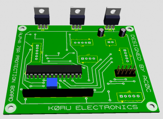 The model of the prototype board was laid out and built by Rob K0RU. A big thanks to Rob for his work on the board. The board is a 2-sided design with most of the R&C implemented in SMT devices to save space. The microprocessor is an Atmel AVR. Not shown in the model here are the various jacks and header pins for the external connections. 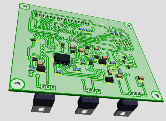
Quite a few mods were made on the fly to the PCB to accommodate last minute additions and changes. CONSTRUCTION DETAILS 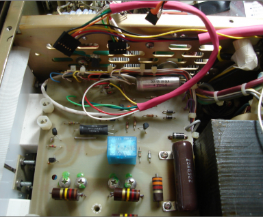
The connections to the amp's circuitry is mostly concentrated on the Alpha main PCB. There is a little daughter board that sits on top of a Lexan cover. The cover has a copper mesh covering it to provides a solid ground for the board and additional RF isolation. The Lexan has a extremely high breakdown voltage as well. 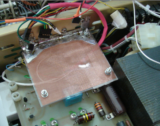
The LCD can be mounted either as the external control head, or directly on the board as shown below. A programming port prevents the need to remove the uP each time. Shown below is a programmer connected to the board. 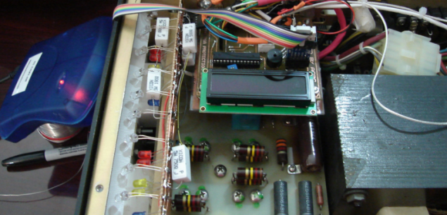
The board I/O ties to the ribbon through a big type 31 ferrite. The Lexan insulates the ribbon cable and the HV as the Lexan sits on top of the bleeder resistors - it extends on the right side of the case to enclose the caps isolating the ribbon cable. There is a cutout on the Lexan where the surge resistor vents (top, center). The ribbon cable for the control head runs down the side of the case and exits the bottom of the normally in place top U-cover. I just don’t screw the bottom screws in at the bottom which prevents squeezing the ribbon cable to the case. In this way each item is removable so the board can be services outside of the amp. 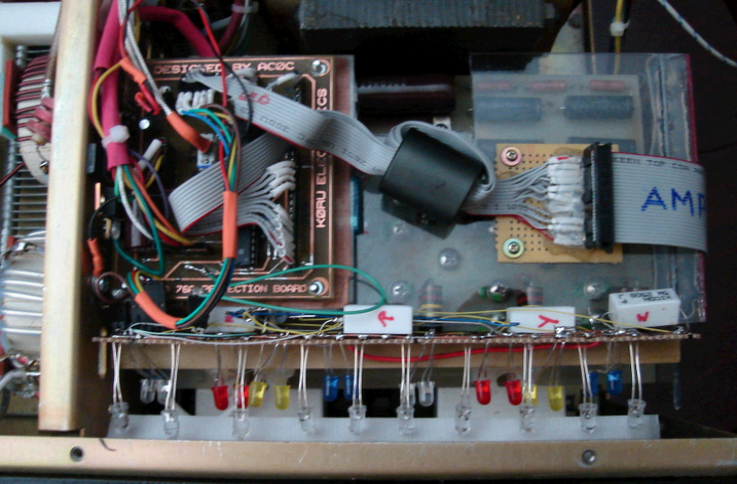 The transformer sensor can be seen under the nylon tie strap. Thermal compound is used between the sensor plate, the transformer and the thermistor to ensure a good temperature exposure to the thermistor. The white wire leading off and to the lower right was a DVM temp probe used to confirm the accuracy of the internal board's readings. 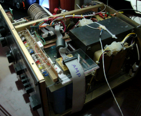 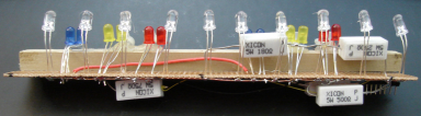
Several additional LED's were added to accommodate various error or information conditions that the board can generate. Yellow - Grid warning threshold reached Red - tube or transformer warning temps reached Blue - transmit mode (shown below) Green - standby or tube warm-up cycle active There is a transistor cutout that lowers the brightness of the white LED when any of these (except transmit mode) is active to avoid a washed-out color look. Once the final LED number and positions are established, the board can be laid out and a PCB used to replace this breadboard stick configuration. 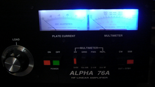 The QSK relay on the right side was an earlier addition. The temp sensors on the left collect the individual tube temps are high temp thermistors in parallel. The temp sensors are bypassed at the junction to ground with a 0.1uF cap. And the shield of the thermo sensors is grounded at the junction of the RF compartment and the power supply compartment. These measures, along with bypassing and filter nets on the control board's I/O, helps to keep the RF compartment's RF levels from causing trouble with the logic side. 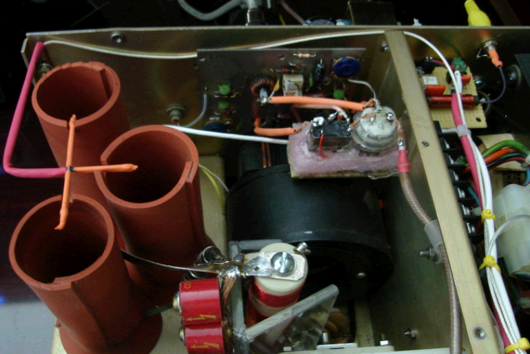
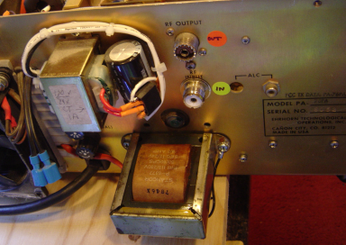
There is not much free space in the cabinet so the power supply that runs the protection board is externally mounted. There’s a Hypersil version of the transformer but this unit has the standard EI type. And the stock LV power supply runs only when the unit is switched on. I wanted to have the fan control run after the power was switched off – so that, depending on heat of the tube/transformer, the fan would continue to run until these components reach a decent (lower) temp. That forced the decision to use an additional supply and the space constraints forced it's location. 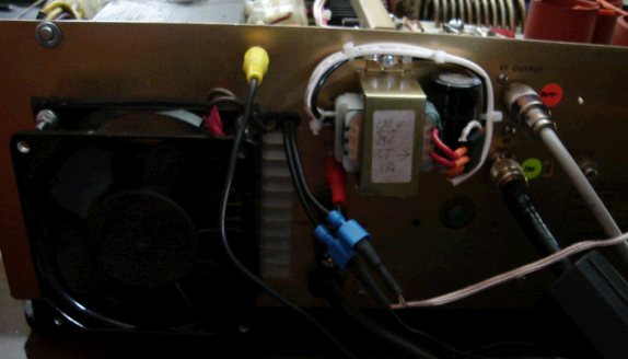 The yellow cable is on a new RCA jack - the output feeds the TX inhibit line to the rig. The two blue connectors are tied to an exhaust fan that is mounted to the underside of a shelf above the amp exhaust ports. The black muffin fan on the left is added as well. It serves to pressurize the chassis and keep air moving over the transformer area. In this way all 3 of the fans involved are under control of the amp's variable speed fan supply. The yellow cable is on a new RCA jack - the output feeds the TX inhibit line to the rig. The two blue connectors are tied to an exhaust fan that is mounted to the underside of a shelf above the amp exhaust ports. The black muffin fan on the left is added as well. It serves to pressurize the chassis and keep air moving over the transformer area. In this way all 3 of the fans involved are under control of the amp's variable speed fan supply.
The only other change to the back is a swap of the stock RCA input jack with a SO239. Front view of the control head unit shown here. The black button currently toggles the diagnostics (actually the raw ADC readings). But I’m not sure it will remain that later. The blue button toggles the standby function. The A76pa has a standby function but it involves a funky simultaneous pushing of the CW/SSB voltage level on some 25 year old switches. I wanted something faster and easier. 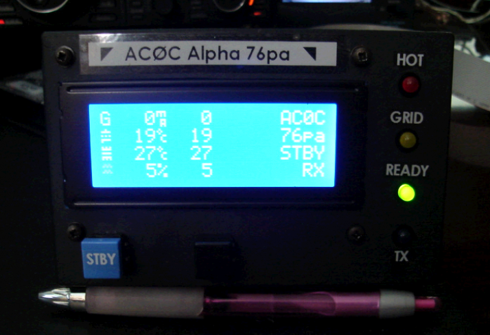 This is the view in the normal mode. An alternative screen shows the actual measured values of each sensor and was handy in debugging the firmware. 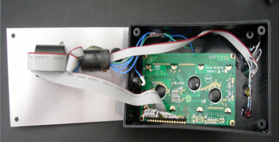
You can see the custom LCD characters on the screen left side. They represent (top to bottom) grid current, tube temps, transformer temp and fan speed. The 2nd column of numbers represent the peak values of the various items from the last transmission (except for the transformer temp – which is for the current power on cycle). Internally, the box is of an unshielded variety however, connections first route through a couple of turns of big type 31 ferrites to keep any RFI gremlins from trying to spoil the party. Down the Road... After running the modified version of the amp for about 18 months now, things are for the most part working quite well. The multi-revision and it's patched up PCB is a bit finicky to handle if any work to the main amp PCB is required but with care nothing has broken or proven unreliable. There have been two small failures in the mean time, both from the original amp. I noticed a HV sag in the SSB operation position. Subsequent checking of the PS caps found one cap reading zero capacitance and another 12 uF. Original values are about 200 uF. A replacement set was had from Harbaugh and the swap done easily and quickly, thanks to the screw mount style of the caps. I feel fortunate in that most cap failures are of the type you can hear when one explodes! 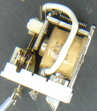
And in the latest of the strange, the amp started to power off when in warm-up at random times. The 2K/SB200 kept me in the QRO class and so the repair was not urgent. A few weeks later when I got back to looking into the problem, the amp would not power on at all! The problem was traced to the step-start relay (shown at left) but discovering that was harder than it should have been. Along with the intermittent and sticking relay, the SS fuse had also blown at some point. Unfortunately, I had relocated the SS fuse to a point below the AVR board and did not notice the popped fuse until tracing the AC path. One side of the relay contacts had a semi-permanent bridge of material (yellow circle) shorting one pair of the contacts. I'm unsure of the root cause of the failure. My guess is that in the 25 years of life, that relay has seen it's share of power cycles and eventually started to show a higher initial contact resistance. Higher resistance lead to more heat and a path toward eventual failure. The relay was replaced with a set of series-connected Omron SPDT 12v relays from the junk box. And the SS fuse is relocated to the chassis floor, just above the front right foot retaining screw - easy to see and easy to access! The '76pa is back in action and has helped me bag 7O6T for a new one on 20 and 15. With the new PS caps and the SS relay swap, Mrs. Jones is as smooth and sexy as she ever was. New Jugs for Mrs JonesSwapped out the three 8874 tubes for a pair of 3cx800. The conversion was mostly simple involving a filament transformer, silicon chimenys and tubes. The amp makes with 50w drive what the trio of 8874 did with about 75w drive. 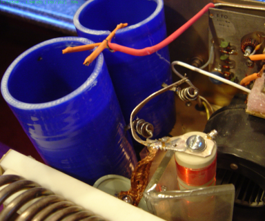
The transformer was a junkbox favorite from a good friend. It's 12VAC @ 4A and runs 13.47 VAC RMS loaded - which is perfectly in the center of the Eimac spec! 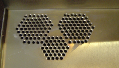
While I was inside the amp, I swapped out the old doorknobs for this big Soviet-era unit. The old doorknobs never complained, but they were not really built for RF service unlike the new unit. Some additional venting holes were added although I'm not sure they were needed. The 3rd (smaller) hole is blocked off (not shown here). I will pull the 3rd thermistor off the heat sensor probe later as it's unneeded. But that would require a bit of firmware adjustment so it's a project for later. Tank Adjustments The 3CX800 tubes have higher Cout, a larger surface area, and combined with their location close to the chassis result in an increase in net output capacitance preventing proper tune on 15-10m. As a result the amp's efficiency was poor, with a lot of heat being generated compared to the RF power output; the higher the frequency, the more severe the problem. This kind of stray can normally be offset by adding a small amount of series inductance between the anode and the tune cap, but that was not working in this case. So more extreme measures were going to be needed. The Alpha tank is setup as a PI-L type, with a 200 ohm intermediate impeadance (based on measurements of the L toroid). Putting the measured tank values into the excellent GM3SEK tank design spreadsheet, it looked like some adjustments to the taps on the tank would fix the problem, in conjunction with a 0.55 uH series inductor mounted in the tune cap/anode line. 20m: move tap RIGHT 1 15m: move tap LEFT 1 10m: move tap LEFT 2 |