An "unofficial" modification to the venerable N2PK VNA For the FT-2000 filters project, I needed VNA functionality in the 70 Mhz range. The N2PK is good to 60 Mhz but then it quickly rolls off. That limit is by design . In the stock configuration, the N2PK will deliver typical dynamic range figures of about 120db over the 60 Mhz frequency range. The modification summarized here allows the upper frequency of the unit to extend to about 80 Mhz, albeit with some tradeoffs in dynamic range - the unit will have a dynamic range of about 90db at 70 Mhz with the suggested oscillator. The modification is "unofficial" because it does not meet Paul N2PK's definition of a proper modification - which would be to extend the range with no compromise in functionality. Paul was helpful and while the modification does not meet his level of performance, Paul does agree, however, that for the purposes of our work (filter testing @ 70 Mhz), the modification is adequate to the job as long as we were willing to accept the lower dynamic range capability. The modification has 3 steps:
- Replacement of 148 Mhz oscillator with 180 Mhz version
- Replacement of low-pass filters on the two output lines with filters having a higher corner frequency
- Coupling capacitor and bias resistors added to the board to make the N2PK play nice with the new oscillator
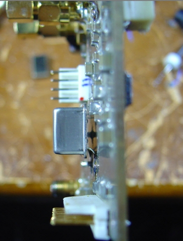
1. Oscillator replacement Ivan Makarov offers some very nice CW 180 Mhz oscillators. See RF Parts on the menu at www.makarov.ca The oscillator was mounted on my older version 4 boards. The N2PK was given to me by a kindly gentlemen who had put some sort of conformal coating on the boards - they were fully functional and the conformal coating keeps things nice and clean. But I did not know what the coating was, so rather than try to remove it chemically, I abraded the necessary areas to gain clean contact with the surfaces - that's the white tint you see in the areas where the work was performed. The modification areas are shown below on this view of the boards' back side. LPF replacement in the two yellow boxes (upper left). Bias divider for the oscillator squarer (center top). And the oscillator feed through pins for power (lower right) and coupling capacitor/osc output (lower left). 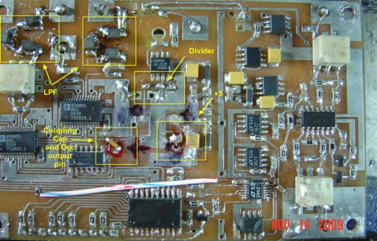
Oscilator feed-through holes. Prior to mounting, holes were put in the board and the backplane releived to prevent short to the groundplane. 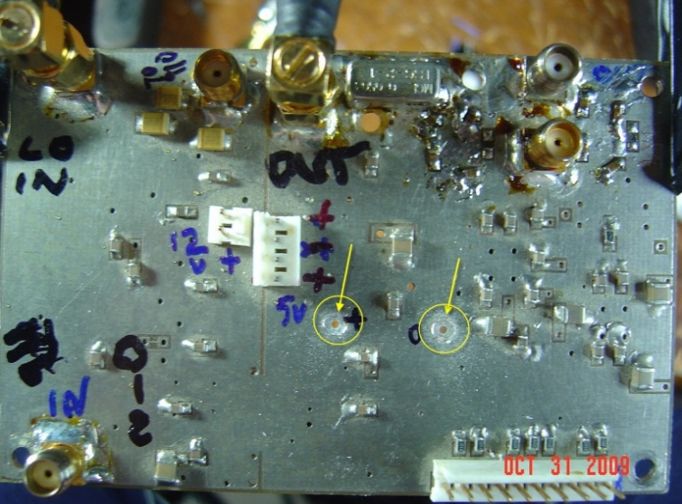
The alignment is a bit tricky but if you drill from the bottom side, then it should work well. Be careful to avoid the top side coupling caps. The oscillator should be positioned as close to the board as is possible - while still allowing for some clearance between the oscillator and the bypass caps. In my installation, the two ground leads were simply bent into an "L" shape and put at right angles and then soldered directly to the groundplane. The markings you see help me to keep from getting things mixed up. They are easily removed with an alcohol swab after the work is complete. 
 2. LPF Filter modifications From page 6 of Paul's schematics (CLICK HERE), we can see the filter segments which need to be modified (yellow shaded areas). 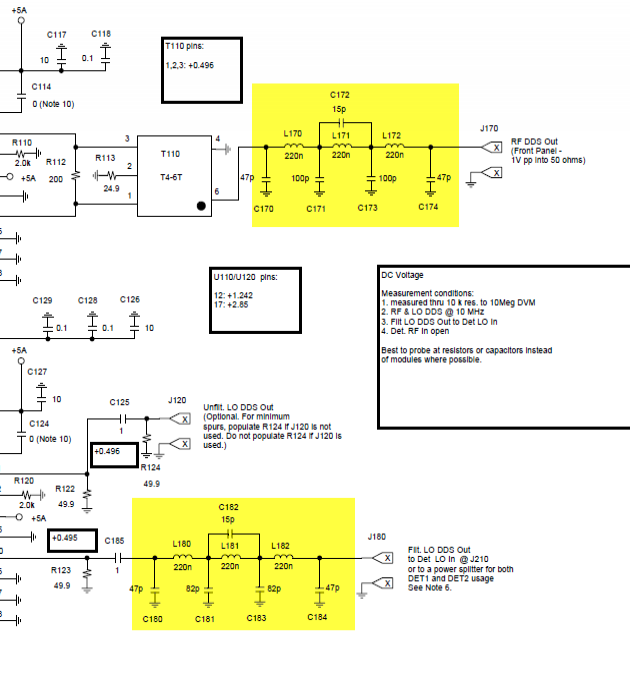
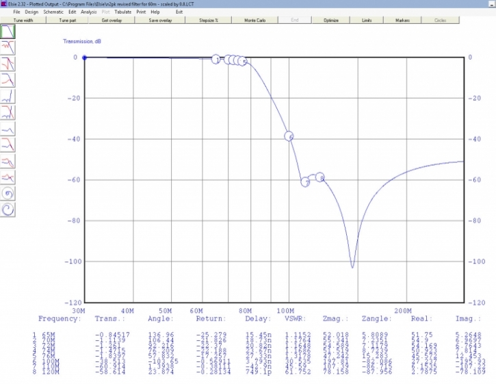
The filter follows Paul's 80% scaling for the center frequency and was optimized in Elsie for a null at the 2nd harmonic. Notice the schematic is slightly different from the original design. Solder the capacitor down to the board first, then the inductor on top of it - to accomidate the added capacitor on each end of the filter series trap pairs. Part values are shown below. Self-shielding inductors and NPO caps are recommended. Performance plot from Elsie is shown below 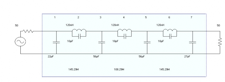
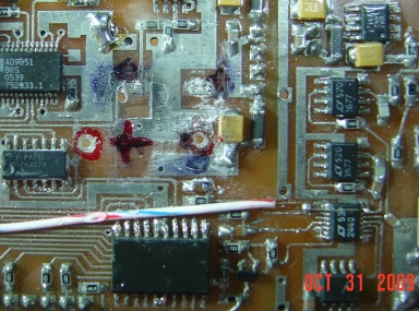
3. Component adjustments Only two other changes need to be made to wrap up the rest of the project... - Connect a 0.1 uF cap from the output of the oscillator to the existing input of the flip flops - this serves as a DC block.
- Change R151 and R153 from 1K to new values of 10K 1% to form a voltage divider from +5 and ground - the center of this connects to the flip flop input side through a 2K series resistor if you follow the schematic. This serves to bias the DDS and the flip flops just right.
4. Other comments The quality of the N2PK's performance at this higher frequency depends on a lot of factors. The DDS output continues to drop with frequency which is an issue that we cannot address. And the "inverted alias" which comes down ends up getting close enough to cause problems as we get closer to 80 Mhz. The filters are really trimmed for a 75 Mhz corner frequency and as you press above that, expect the dynamic range to really start to compress. Functionally, Paul has warned that the 74AC74 may not toggle at that frequency - but in my case, the flip flop works great - it's likly yours will work as well. Charlie W5VIN used Markaov's v5 board for the mod and 2009-vintage components and his worked FB as well. If your AC74 does not toggle for some reason, it's simple swap to make and a newer vintage chip may work fine - not because the AC technology has improved, but due to the movement by IC makers to march toward smaller geometry as a cost reduction step. Smaller geometry means, all things the same, higher toggle frequencies. The 74AC74 sold by ST has a 300 Mhz toggle frequency per the data sheet and is another option. For thouse wanting to try a diffent method to extend the range, look for comments on 3rd harmonic mixing on the N2PK VNA Yahoo board for details. It requires off-board BPF, squarers and attenuators however, this experimental solution is has the potential of pushing the units performance far beyond what this project allows... 5. Results Plot of the dynamic range (open measurement) in the area of interest frequency for our filters project. 90db is very FB for our filter testing needs! 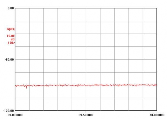
|