Adding a A DDS Sidetone Oscillator and making a few other mods to a great keyer 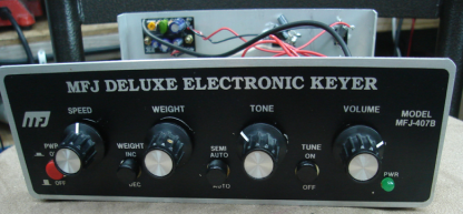
Based on the Curtis 8044ABM, the MFJ-407B is a basic implementation of a great keyer chip. Keyers are pretty low-tech by modern standards, but at the time, it was IC-magic. The chip was first produced in 1986 and was used in many keyers for perhaps 20 years after. The keyer chip provides Iambic keying with full weight control as well as a built-in sidetone oscillator - which is the focus here. And it has both positive and negative keying outputs - meaning I can run the keyer against both the TS-820S (negative grid-block keying) and the perhaps more "modern" FT-102 (positive +5V keying).The I had thought the keyer would be a good match for my TS-820S - and yet another good excuse to get busy polishing my pretty pathetic fist! Unfortunately code from the keyer's sidetone was accompanied with a pretty bad click-thump on every tone. Yuck! THUMP THUMP THUMP - The ProblemPulling the lid off, I found a small 1W LM358 amp had been added - which may have been stock with the MFJ board - or not. I could not find an original MFJ schematic but it looks like the MFJ implementation follows the Curtis datasheet values closely. The small amp sits on a daughter board on the back wall of the keyer leading me to think a prior owner had added it along the way; you can see the amp in the picture (above). It certainly has ample volume even though the sound is far from sweet music that a well shaped CW note should exhibit. Hooking the scope to the output of the chip, part of the problem was apparent right away - the sidetone output from the chip is a square wave and running a square wave into a "linear" off-board amp is going to make for some interesting artifacts as it's pushed constantly into clipping - in addition to the harmonics present in the square wave output to begin with. 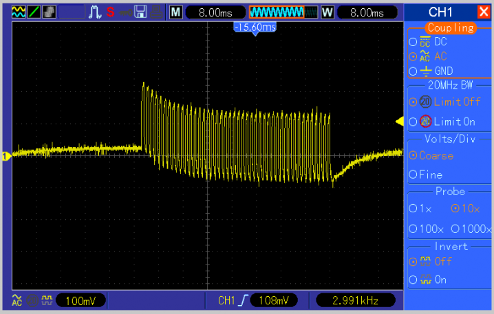
The thump is due to the big DC level offset that is visible at the end of each tone. The AF spectrum of the keyer's output is shown in the graph below - characteristic of a square wave, the odd harmonics are strong and the even harmonics somewhat muted by comparison. 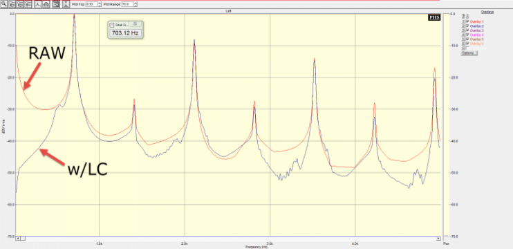
Something would have to be done and my first thought was to try to filter it. My first thought was to stick a simple LC filter on the speaker and see if a brute force method could quiet down the thump - it did to some extent (black trace below), but even with the thump muted a bit, the tone was still poor. FILTERING and the DDS "FINAL SOLUTION"The location of the spectral trouble of the keyer chip's sidetone is pretty specific - problem #1 is the relatively low frequency but massive DC offset which drives the need for low end (under 100 Hz) attenuation. And problem #2, on the high side, finds that nothing really is present until the second harmonic frequency. I prefer a sidetone of around 600-650 Hz so the 2nd harmonic is at 1200-1300 Hz. And because the source is a square wave that means the 2nd harmonic is lower in amplitude compared to the odd harmonics suggesting the next "big" amplitude peak would be at 1800 Hz. These are confirmed by the SA plot (above). So the ideal filter would whack the low end, and roll off the high, as genitally as possible to avoid impacting the rise/fall times of the individual keying element. Filtering anything passes for fun around here so my initial solution was to try the Hi-Per-Mite CW Filter; available from the Four State QRP group as a kit. The results with that were OK but not quite what I was looking for. The Hi-Per-Mite provides a nice pretty good 100-150 hz passband - but that fairly tight bandpass comes at the expense of some rounding of the impulse response of signals fed into it. The ideal keying waveform rise/fall times cannot be too fast - or it will sound "clicky." And it cannot be too slow, or it will sound "mushy." Something in about the 4 mS rise/fall time range is very nice. Generally speaking, the higher the filter Q, the more delay there is and the more aggressive the rounding of the leading and falling edge impact is. As bandpass filters go, the Hi-Per-Mite filter is a low-Q type, but it's still too aggressive for this application. I suppose the same circuit topology could be used with different values and retain the original PCB, but I wanted to see what other alternatives were available. Maybe something I had not thought of would be a better alternative? Digging around the internet I found several passive type filters using the old 88 mH telephone toroids and some other odd-ball types of filters. There are tons of active and SCF filter options available - with plenty of free for the download software that helps design that sort of thing. Unfortunately it did not look like any simple combination of active filter scenarios was going to give the tone I was hoping for. I ran across a web page by WB0RIO Forrest Cook which uses a triangle waveform oscillator feeding a voltage controlled amp and filter with a nice looking waveform. No kit or PCB was available so it would be a breadboard project. http://www.solorb.com/elect/hamcirc/sidetone/ Some comments on that circuit included modifications made by W9AC Paul Christensen. In discussing the circuit with Paul, he told me that the design worked fine and sounded good, but that he had recently switched to an audio DDS sold by N4YG that worked pretty well. http://www.n4yg.com/STCPO.html A kit generally beats breadboard at this QTH so I bought the N4YG DDS kit and it looked good on the scope - although the rise time was too long. The sound being sweet and clean but a bit mushy with higher speeds due to the slow rise/fall rate. I suppose that for learning CW that's not a problem (and that's really what the circuit was designed for) - but for any speeds from the mid 20's or higher sounded mushy by my ear. In discussing it with Joe N4YG, he was kind enough to tweak his firmware and sent me out a modified chip a week or so later. Great response!!! With the new chip; the waveform looked great! And it sounded great as well. The DDS was mounted in the MFJ on a couple of screws that were stuck in the back side of the MFJ board and serve as risers. I reused the original volume control but swapped the 1M MFJ pot for a 5K unit that comes with the DDS board. The 1M pot may have worked as the tone control, as it's just a voltage divider which provides a voltage reference that is read by the DDS ADC. The ADC has a pretty high Z input but with the MFJ disassembled, it was easy to swap the pots. I padded the pot with fixed resistors on both side to restrict the resulting tone range to cover 500-850 hz (it will cover about 200-1500 without the limits) just to improve the granularity of the pot in picking that perfect pitch for the sidetone. Also visible in the photo below is a 3-terminal 9V regulator - which allows me to feed the keyer with the shack's roughly 12v bus and not fry the Curtis chip which has a 12V absolute maximum rating. The DDS is "keyed" by tying into the driver transistor hanging off the Curtis chip's output. The DDS needs a 5V signal and so I used a MOSFET 2N7000 to serve as my level translator. 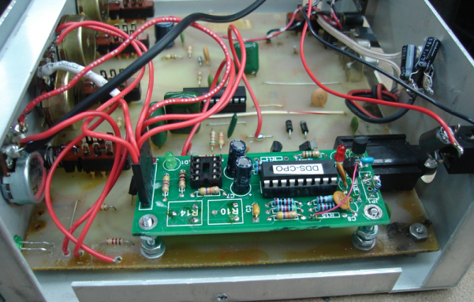
Seen below is a close up of the leading edge of the DDS chip output waveform, measuring about 5 mS. Note there is no DC offset to the 2.5V no-signal bias on either the leading and trailing edge eliminating the thump sound. The falling edge has the same 5 mS roll-off. 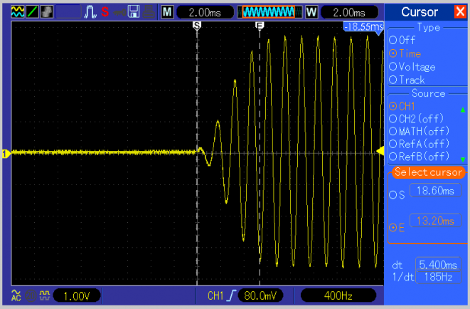
The steady-state DDS output has a nice sine wave characteristic. There is some switching-related artifacts present in the DDS output but those are a pretty high frequency and as such are handled by a simple RC filter - part of the DDS PCB. In the N4YG implementation, an Atmel AVR uP drives a set of 8 resistors - the sum of that network reconstructs the waveform. 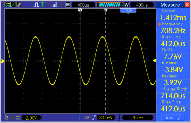
The final result of the DDS addition, comparing the original Curtis chip sidetone (red trace) with the DDS output (purple trace), is given below. There is some 2nd harmonic content present (-35 dBc) but it's about 10 db improved relative to the square wave of the Curtis chip. The higher harmonics, and importantly the near DC component, are both absent with respect to the general noise floor. 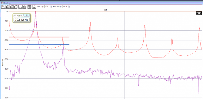
OTHER MODS In addition to adding the DDS sidetone module, a few other mods were made to improve the keyer's utility here in the shack: 1. 9V regulator added to the case, plus 12V dongle out the back 2. Swapped keyer jack to match keyer 3. Added external jack for speaker 4. Removed battery clip 5. Replaced front LED SPECIAL THANKS Thanks to Bill Carver W7AAZ and Paul Christensen W9AC |