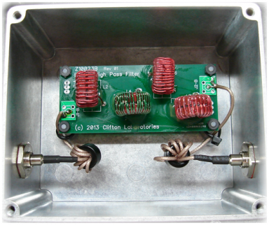
Bringing out the newest big-gun and taking aim at our local AM BC station's 1670 KHz carrier BackgroundIn a prior bench exercise, I took a look a Jack Smith K8ZOA's Z10022A high pass filter. It's designed to give maximum attenuation to the US AM broadcast band. With it's 9th order Chebyshev topology, I measured 90 dB at points here on the AC0C bench. So when I needed another HPF for the shack RX antennas, Jack was the guy I called. Around here, the strongest station is found with a 1670 KHz carrier frequency. And for some of the receiving antenna combinations, we can get some inter-modulation products that show up in the 160m band as a result. The solution is to cut down on the broadcast band signal levels enough so that the IMD products remain below the noise floor. Unfortunately in my case, that poses quite a challenge for the Z10022A which has a pretty gentle roll-off. Fortunately, Jack has the solution just for this kind of situation. The Z10023A HPF has a 7th order elliptical (also known as Cauer) design which trades off ultimate attenuation for a more rapid transition band skirt. One was ordered up and in the next week was delivered and put on the bench. I measured about 18 db of attenuation from the Z10023A at 1670 KHz.  While the filter did eliminate my IMD problem, being the tinkering-type, I had asked Jack if I could fiddle with the filter a bit to push the "knee" of the filter up a bit in frequency - and thereby move the 1670 KHz carrier of concern further down the transition band. While the filter did eliminate my IMD problem, being the tinkering-type, I had asked Jack if I could fiddle with the filter a bit to push the "knee" of the filter up a bit in frequency - and thereby move the 1670 KHz carrier of concern further down the transition band.
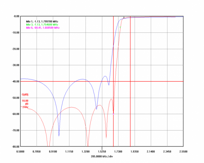
Jack laughed and explained that the filter components are trimmed by hand via adding padder caps or adjusting turn spacing on coils to bring each filter pole onto the exact mark. However, Jack had some great news. He had just ordered the first production lot of boards for a "B" version filter which is a 9-pole elliptical design (vs. 7-poles in the "A" version) and asked if I would like to try that? Of course! The new "B" rev filter arrived in the mail a couple of weeks later and I was able to benchmark both the "A" and "B" versions side-by-side. ResultsLooking at the attenuation levels, the "B" design has about 20 dB more attenuation across the entire AM broadcast band compared to the "A" design. And at 1670 KHz where my local station's carrier was to be found, the "B" rev has nearly 40 dB more of attenuation. While the "A" would have done the job for all but the toughest cases, the "B" literally takes the attenuation game to another level. Very nice results indeed! For more details on all of Jack's filter offerings, take a look at www.cliftonlaboratories.com/current_products.htm Looking at the VNA data, the next graph below is a transmission plot comparing the two Z10023 versions. The "A" version in BLUE color. And the "B" version in RED color. At 1.8 MHz, the filter has a loss of just over 1 dB; and less at frequencies above that. 
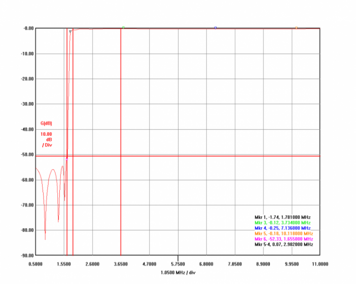
This receiving antenna would be used in some cases for bands other than 160, so I took a wider frequency scan here to ensure the passband was clean. We can see from the graph below that the filter remains flat out beyond 30m (the highest frequency I expected to use this RX antenna) without any strange behavior. Filter insertion loss on the ham bands is well under 1 dB after clearing into the passband at the bottom of 160m. 
|