Targeted Attenuation for Adjacent Bands As explained in the SO2R Math page, filtering is needed between the two rigs to prevent physical damage to the RX front end and to prevent the kinds of high-signal overload conditions like desense and IMD - as well as containing harmonic energy. A very handy tool for adding a bit of band-specific filtering where needed is found in the coax notch trap or stub trap. The Bible of trap design in the contest station environment is W2VJN's book Interstation Interference. The traps used here are documented in the book. Click HERE for more from the book seller's web site. Show here is a 40m example of how coax notch traps can augment the BPF for improved attenuation on the adjacent 80 and 20m bands. Shorted Stub TrapFor the 20m trap, we use a shorted type trap because the 40m operation frequency is below the 20m trap frequency. In this case, the physical construction of the trap is a length of RG-11 coax with a PL-259 crimp-type connector on one end. And a short placed on the other. The frequency of the trap is determined by the coax length. A N2PK VNA was used to trim the trap to the exact length needed to place the null point right on frequency. In my application, the primary contest mode is RTTY followed by CW - which covers a range roughly 14.000-14.120 MHz in the typical case. So the ideal null point for the 20m trap is 14.060 MHz. The VNA plot shown below gives the performance of the completed trap. We can see the trap is ideally tuned with it's peak attenuation right on 14.060 MHz. And the impact on SWR at the operation range of 7 MHz is negligible at 1.04:1. 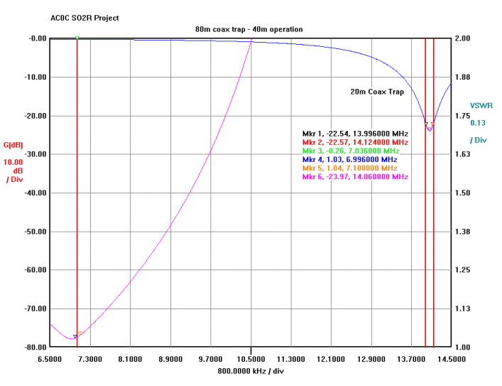
RG-11 has a copper clad steel core which is easy to solder too. So I started with a bit of copper mesh soldered to the center conductor. Then the mesh was cut a few times to make folding easier. 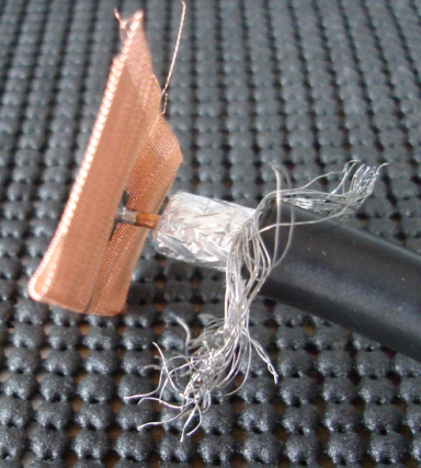
The aluminum shield braid is folded up first, then the copper mesh folded down over that. And finally a clamp is placed on top as the aluminum cannot be soldered too easily. The end should be insulated and some plastic tubing that slides over the end serves the purpose very nicely - giving a clean and very RF-tight finish. 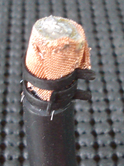
Open Stub TrapFor the 80m trap, an open style trap is used because the 80m trap frequency is below the 40m operation frequency. The CW/RTTY range is 3.50-3.60 MHz so the target is 3.55 MHz. The trim and response is similar to the 20m example above. 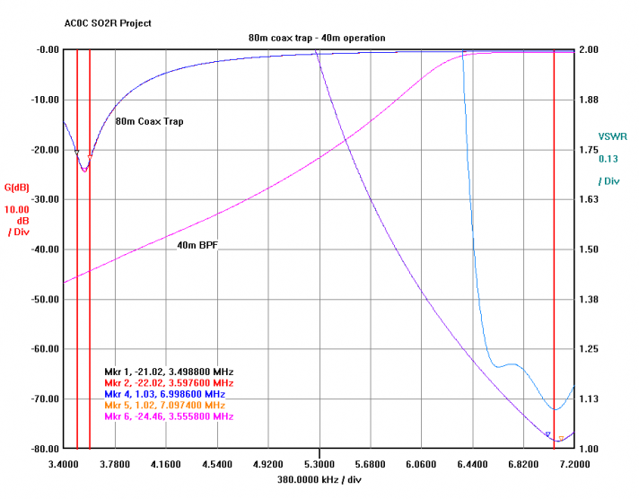
An open stub needs to be shielded to prevent leakage. And high voltages may be present. My solution to this was to strip the foil back a bit. 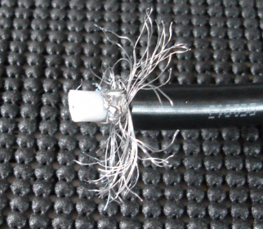
Then a bit of coax insulation is cut as shown in the picture below. I fill the insulation with a hot-glue gun to hold it together and provide a bit more insulation. 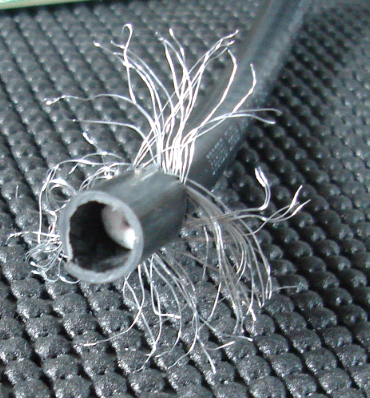
Then a bit of copper mesh is cut and fit over the end. A bit of solder tacks the assembly together. And finally, the copper foil is clamped to the aluminum shielding and covered with a bit of plastic tubing to provide insulation to the tip - completing the trap. 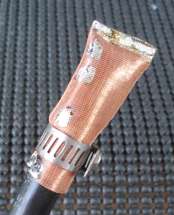
Combining the 5B4AGN W3NQN BPF and Coax Traps For reference, the VNA plot below shows the combined coax trap attenuation (BLUE line). The impact of the traps at 40m is negligible. The W3NQN style BPF filters are shown in PURPLE - about 40 db or so at 80m, and 60 db at 20m. 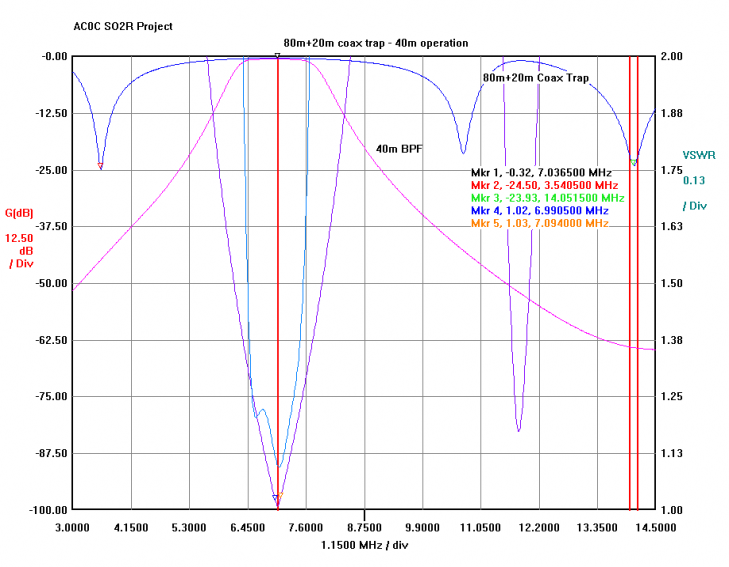
When the BPF and traps are combined (PURPLE line), the impact is significant. 80m attenuation from the set is 65 db and 20m is about 88 db! Adding traps makes a good filter better. 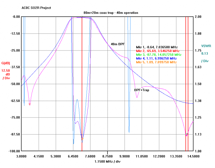
Other Trap ConsiderationsCoax traps can be rolled up together. For maximum isolation, they can be put into a shielded container (large paint can?). Some guys build switching boxes with the traps connected to an antenna switch for easy shack-level selection. In my case, with the variety of monobanders, I can put the traps at any point along the antenna feed prior to the switch and no further switching will be needed. Voltages vary along a transmisison line. For maximum attenuation, the ideal placement of the trap is at a voltage maximum. The graphs shown above represent the worst- case in that they are tested at the VNA termination . The ideal placement of the trap (at the antenna feed-point, or at the antenna switch header) will need to be tested. Trap attenuation depends on resistance. Generally speaking, the larger the center conductor, the better the performance. 75 ohm and 50 ohm coax is equally suited for trap construction. Trap trimming can be done with a rig but it's much easier with something like a MFJ-259 or VNA. 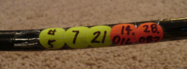
Keeping track of which stub is best for each application was tough. Then I started labeling the stubs with a sequence including an assigned stub "serial number" and the "pass" band with a green dot. And the peak attenuation points of the nulls with red dots. Dots are covered with clear tape to protect from abrading. I keep the VNA plot on file and reference it with the stub number. Example of the #5 stub in the photo below. K9YC's comments on coax notch traps: http://audiosystemsgroup.com/Coax-Stubs.pdf K1TTT's tech notes page - look for the section on filters. Several great coax trap note links here: http://www.k1ttt.net/technote/techref.html And for some very serious multiple coax trap combinations, take a look at the E73M web page for some excellent Elsie design examples and amazing notch results!. An example of a 15m operating band multiple-trap style filter here: http://www.e73m.com/NotchCoax15m.php |