Adding topband to a full sized elevated 80m vertical and putting N6LF's QEX data to the test This antenna started out as an 80m vertical - with160m capability added as a secondary consideration. In reflection, I'm very glad to have added the 160m operation as that is a fascinating band. It's now on it's second version (v2), with a conversion from a trap-based to relay-based band selection and full matching net now complete. 
From the diagram, you can see that 50 ohm feed line runs to the 2x6 switch (mounted on a tower about half way to the vertical), and from the switch onward to the vertical, it's 75 ohm RG-11. The LC network is a few feet below the vertical's base. It's an elevated structure, with 10 elevated radials at head-height. A control line runs from the shack to the vertical allowing some relay switching which engages the cap hats to shift the resonant point of the vertical from 80m to 160m - and to likewise set the L/C for the band in operation. Dual-banding OptionsThere are a lot of ideas on how to build a dual-banded antenna. But most of them don't start out with a 80m vertical and then adding 160m onto it as a retrofit. The first version of the vertical found me adding a trap and some cap hat wires to provide 160m operation. It was functional and a good performer. And this season, I wanted to fix the big problems discovered since it was put up 9 months ago. Trap-based version 1 worked fine - but I had quite a bit of SWR drift on 80m as the trap warmed up from RTTY contesting duty - a real headache as the SWR swing was big (from 1.3:1 to over 3:1 depending on how long the key was down). And I did not initially build any kind of a matching network so the SWR was off for most of 80m, and all of 160m. But with 600+ feet of coax between the shack amp and the antenna, SWR is never really a big problem thanks to the line loss which tends to suppress the magnitude of SWR problems. Heading into the contest season this year, I wanted to fix the match and solve the SWR drift problems. So a couple of months serious thought was given to the various ways this could be addressed. Not because it's a hard problem - but rather there are a lot of options here, and all of them have their pros and cons. You can however roughly categorize them as either trap-based or switch-based. 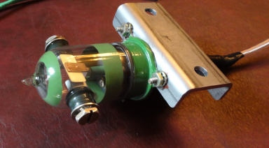
Having used a trap the first time, I thought the solution would be to use a bigger trap (which worked perfectly in the attic build earlier) with vacuum caps and 1/4" tubing. Traps can work nice, but they are not without trade-offs. The resonant trap in use with v1 of the vertical caused bandwidth on 80m to be narrowed to about half the bandwidth without the trap. Non-resonant trap variations (moving the trap out of band and off resonance) had problems as well. A LC net was going to be required in any case, but the interaction of the vertical and cap hats on both bands was significant which may have required some length adjustment of the vertical section (not an easy task...). Then there is trap loss. And component drift due to heating (a problem for RTTY contesting mostly). Lastly, the fact that the trap is at the end of pole means trap adjustments or repairs require taking the vertical down for service. So while the trap was workable, it did not seem to be "better" - rather, it was going to be "about the same" although most certainly more stable with right-sized components used. Another option was to use a relay. I had grown very comfortable using relays for precision antenna control in the attic. However, most of those were at the high-current, low voltage parts of the antenna. Putting a relay at the HV tip of an element was covering new ground (for me). In this case, the idea would be to have the cap hat wires electrically connected to the top of the 80m vertical, changing the resonant point of the vertical from 80m to 160m. A switched relay solution would side-step the trap's bandwidth shrinking side-effects and potential losses. But a relay switched solution was not without it's cons as well. 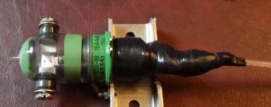 The end of the vertical is a high-voltage point on 80m and that means potentially thousands of volts across the relay contacts. A control line would run along side the vertical up to the relay as well - and that requires very good differential and common mode choking to keep the feed line clear of RF - a challenge since the control wire runs along the outside of the vertical element with zero spacing! Power for that relay would need to be run from the shack. A bias T would not work as easily since the coax from the vertical does not run in isolation back to the shack - it stops about half way back to the shack at a 2x6 So2r antenna switch. And lastly, some kind of L/C network would be needed to provide a match, just as in the case of the trap. I liked the idea that if the relay could be made to work, potentially better performance (both in terms of natural SWR bandwidth and reduced losses) was possible. The end of the vertical is a high-voltage point on 80m and that means potentially thousands of volts across the relay contacts. A control line would run along side the vertical up to the relay as well - and that requires very good differential and common mode choking to keep the feed line clear of RF - a challenge since the control wire runs along the outside of the vertical element with zero spacing! Power for that relay would need to be run from the shack. A bias T would not work as easily since the coax from the vertical does not run in isolation back to the shack - it stops about half way back to the shack at a 2x6 So2r antenna switch. And lastly, some kind of L/C network would be needed to provide a match, just as in the case of the trap. I liked the idea that if the relay could be made to work, potentially better performance (both in terms of natural SWR bandwidth and reduced losses) was possible.
In the end, the relay won the day; the decision made all the easier by having a suitable relay in the junkbox, collecting dust. Shown in the two pictures above is the actual relay used. It was mounted on a scrap of SS pipe clamp. Within the black tape are a clamping diode, parallel cap and series inductor to address differential mode currents. The components were encased in hot-glue and then tape wrapped. More details on the vertical's construction are found later on this page. Elevated Radial Design Choices and RationaleThe radial structure is continued from v1 and has served fine. A complete review of the radial system follows. Elevated radials are the focus of some huge debates in the antenna building community. Traditionally they are quarter wave in length, 1/8 wave above ground and said to be equal too - or much worse performers (depending on who's talking) - than a spread of ground based equivalents. Fortunately, N6LF published two articles in QEX which debunked a lot of these rules-of-thumb. For more info on the N6LF QEX articles, see http://www.antennasbyn6lf.com. I wanted to use elevated radials for this antenna because the antenna will eventually be replaced. As I consider it a temporary antenna, elevated radials would make removal very easy. And I believed that the performance of the vertical could be as good as the in-ground types if made with care. There are 3 radial-related design features of this antenna that are worth some explanation:
1. Radial height - the "1/8 wave above ground" rule of thumb was shown by the N6LF data to be not necessary. In fact, his data says there is very little loss difference between radials spaced off the ground by just a single foot to those spaced much higher.
As a practical matter, the radials for this antenna were set at a height of about 7' which allowed 2x4x10' studs to be used as the support element for the radial ends with about 3' of the stud buried. That keeps them above the heads of the guy cutting the grass (me) and any deer that may be wandering around. From a performance standpoint, 7' is about 0.02 wavelength on 80m, which incurs no significant penalty due to inadequate height above ground - as seen in the N6LF chart below. 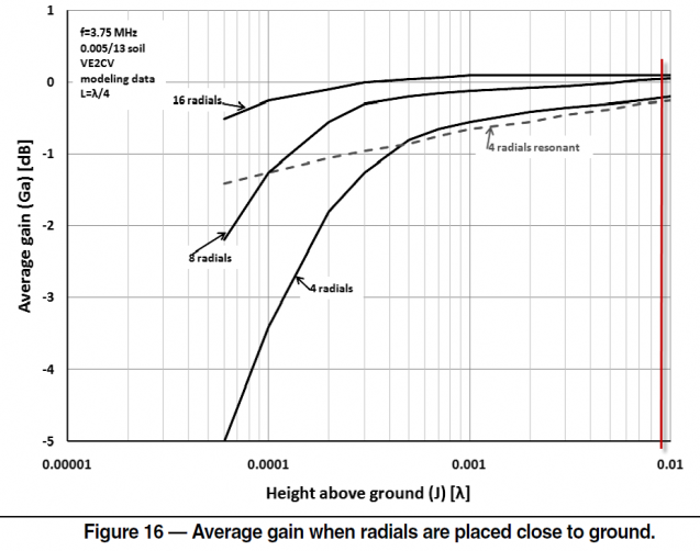
 2. Radial length - perhaps the most mis-understood elevated radial myth is the need to use exact quarter-wave- length radials. 2. Radial length - perhaps the most mis-understood elevated radial myth is the need to use exact quarter-wave- length radials.
The radials can be of any length - N6LF showed that deviations far away from quarter wave provided very little penalty. There is some impact on performance depending on length. However, the advantage to using non-resonant radials is significant and in my assessment, easily overcomes the very small potential performance hit. The advantage of using non-resonant radial lengths is that electrical symmetry (equal currents in all radials) is much easier to achieve. A quarter wave radial has a very low impedance relative to non-resonant lengths. As a result, a small change in length between nearly resonant radials creates a large change in current sharing between the radials. Its likely the case that even with quarter-wave-length radials that are measured to be the same length, small differences in the ground, variations in length, tension and other variables would all conspire to result in uneven radial currents being present even in the most careful installations. This sensitivity is easy to confirm in EZNEC. Radials longer or shorter than quarter wave have a much greater impedance by contrast. In this case, the same physical change results in much less of a current sharing change. An article by K5IU really helped bring this item into focus for me. Note that radials other than quarter wave will contribute some amount of reactance - but this is easily offset by altering the length of the vertical element a bit to restore Xj=0. For this antenna, the length of 74 feet was convenient given the location of the radial support studs. That's slightly longer than a quarter wave on 80m, coming in at about 0.28 wave length. The same radial serves well on 160m also; coming in at about 0.14 wave length long. As we can see from the chart below (from the N6LF QEX article), the penalty on 160m for the 0.14 WL radials is around 1 dB (worst case assuming poor soil). If the soil is average or good (as is the case here in farm country), then the loss is much less. This means that the length of the radial at 74 feet is workable for both bands, and contributes very little to additional loss (even on 160m) and will be much more robust in current uniformity. 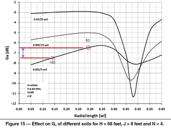
Regarding the impact of the radials on feed point Z, the individual radials are electrically in parallel - which means that the reactive contribution will be divided by the number of radials (assuming they are electrically identical). As a practical matter, the Xj component is the more significant. 3. Radial Count - There are 10 radials on this system.
Originally I planned to use 8 but in a couple of locations, trees were inconveniently in the way. Rather than cutting down the tree, I added a radial and moved the two radials - with one on either side of the tree. Final radial positions were made with an attempt to have a uniform radial spacing but in the final version, about 6 of the 10 are in the NE half of the plane, and 4 are in the SW half.
If currents can be made identical (!), then a few (4) radials are enough to provide good service. However, the more radials, the less important is the need for uniformity . Given the land has a bit of a slope and uniform radial spacing was hard to get exact, I thought 8 would be a fine choice. There is a graph in the N6LF QEX article which helps estimate the impact of radial count vs. resonant frequency as a proxy of influence (below). This graph shows a convergence starting around 4 radials and reaches it's peak utility at around 12 radials. 8 radials as a minimum seemed to be a good compromise choice. 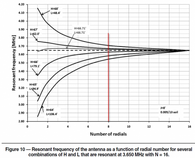
The key point of the elevated radial work done by N6LF makes clear that elevated radials can be very effective if you stay away from resonant values. Radial OptimizationThe radial support and connection method allows the radials to be disconnected individually for testing. The radials are tied to wooden blocks which serving a strain relief function. A few inches of radial form a loop and the end of the radial terminates into one of several terminal blocks. The terminal blocks are connected together with 1/4" copper tubing.. With elevated radials, it's important to try to make them as identical as possible to preserve an even current distribution over the various radials. Measuring the physical length is the normal method with the assumption that the other variations present among the radials (height, tension, lengths, etc) are not significant. However, measuring this seemed to me the better way to go. Measuring the radial currents for balance is difficult - there are 10 radials and a change in the length of one alters the current levels in all the others. So even if you had a method to measure all 10 radials simultaneously, I'm unclear as to what the procedure would be to even out the currents; perhaps the VNA could be configured to provide scan data on a deviation from average currents measured or something. In the end, I decided that measuring the currents would be best used as a confirmation of any trimming effort - not as the actual indicator for the trimming. Another suggestion (used here) was to disconnect all the radials, and then trim each radial so that the resonance points are identical. This allows adjusting the physical length and looking at the electrical result with an accurate instrument (VNA) which allows excellent precision. The idea is that once the radials are all connected, the currents will be evenly divided over the identically resonant radials. However, this method does assume that the resistive contribution of each radial is essentially the same. Specifically, the steps are: - Connect the VNA to the vertical and configure it to measure Xj.
- Disconnect all radials except for the first one. Measure the X=0 frequency. This frequency serves as the target which all other radials will be trimmed to.
- Disconnect the first radial. Connect the 2nd radial. Measure, trim, repeat - until the X=0 frequency is identical to the first radial.
- Repeat this procedure with each remaining radial.
- Connect all radials to the vertical to complete the process.
The process described above was followed and the resulting radials were trimmed to resonant frequencies. The final resonant values were all within a 3 KHz range. Putting that in context: to move an 80m dipole by 3 KHz requires a 1.5" adjustment. The next step will be to measure the actual current variation. I do expect it to be very even. So the final check awaits. 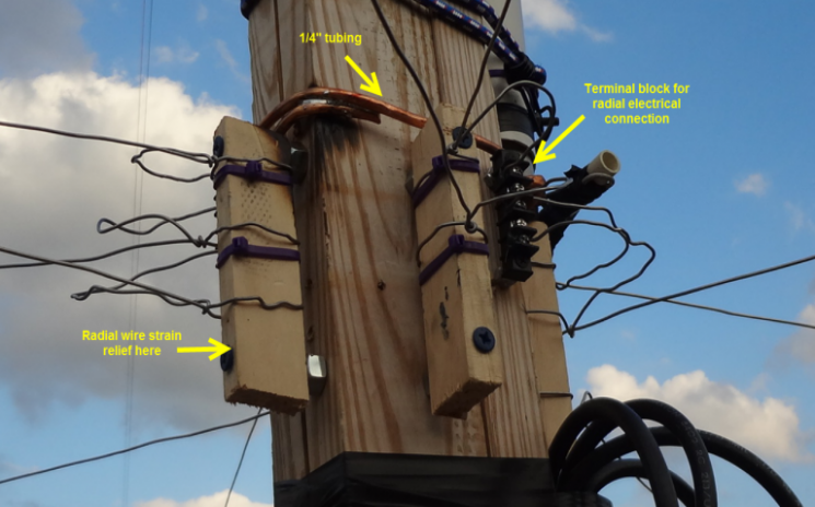
Construction Details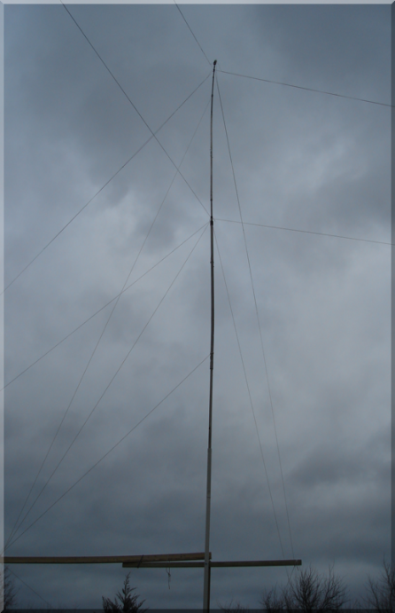
The vertical is guyed at 2 levels. The 3rd and lowest guy set seen in the picture is part of the derrick arrangement (described more below). The vertical is constructed from scrap bits of pipe and is about 2.5" at the base, tapering to about 1.5" at the top. 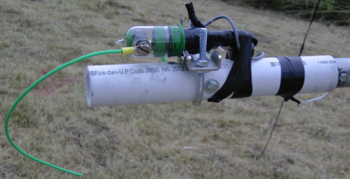
The top of the vertical has a bit of PVC mounted on the end; the relay is mounted to that. The PVC was left from the prior trap use and was convenient in that it provides some insulation function between the relay, vertical top, and the cap hat wires. The top-most guy wires are tied to the mast just below the PVC pipe (not visible in this photo). The gray colored control wire is visible here. It runs down the length of the vertical on the outside; taped in place every 10' or so. 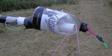 The cap hat wires are supported by the guy ropes by bits of electrical tape. Near the top of the vertical, the cap hat wires are tied together and taped onto the neck of the plastic bottle shown here. The cap hat wires are supported by the guy ropes by bits of electrical tape. Near the top of the vertical, the cap hat wires are tied together and taped onto the neck of the plastic bottle shown here.
The wire lead from the relay extends out through a hole in the bottle top; the cap hat wires are joined at that point. The spacing from the cap hat wires and the top of the vertical is about 6" in total. The bottle also serves as a weather shield for the relay. The bottom of the bottle is taped shut to keep the wildlife from setting up home inside the bottle. 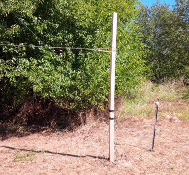
Supports for the elevated guys are built from 2x4x10 treated lumber set into the ground about 2' deep. A small T-post is driven into the ground behind the 2x4 and takes the load from the elevated radials. For the 4 points serving as guy anchors, the ropes tie low onto the 2x4 as seen here. Nylon zip-ties provide about a 6" insulation gap from the end of the elevated radial tip to the bungee cord. The bungee keeps tension on the radial but they need to be replaced each year as they quickly degrade in the sun exposure. 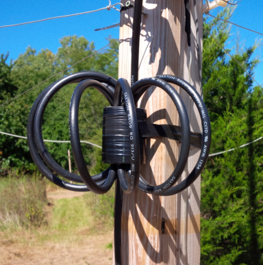
The primary common mode choke is shown here. It's 7 turns of RG-213 through a stack of 7 type-31 ferrite cores. The jumper runs from the base of the vertical to the L/C matching net. The center support post is built from a two 2x4x16 lengths in parallel, with a 2x6x16 on the end. The boards are screwed together along the length. This method results in a beam that resists warping over time - a problem with single-piece posts. 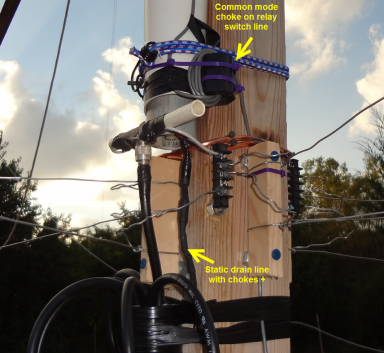
Shown here are the common mode choke for the relay switching line (top arrow). It measures about 5K ohms on both 160 and 80m. Below that, in the black heat-shrink tubing (lower arrow) are the static drain chokes (2x 250 uH) and resistors (2x 2.7 K). The resistors are too low in value but that's what was in the junk box on hand. I'll have to change them to something bigger later. The other end of the resistor is tied to a wire running down the support post, and connects to a 4' ground rod driven in at the base. I had not fully appreciated the static build-up until I happened to pick up the relay wires a few days prior, just as a storm was coming into the area. I can say without any reservation that the wire tested positive for high-voltage according to the nerves on my hand! 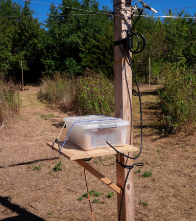
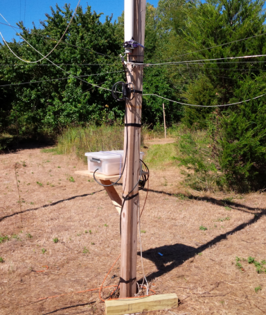
The L/C matching network is housed in this plastic tub. Bungees keep it from being blown off the support in the wind. The elevated radials do not have a ground connection here at the vertical, but do see an earth connection at the 2x6 switch by the tower, on the other end of the RG11 run. 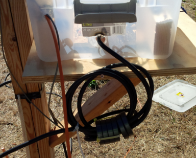
The output of the L/C net runs through another common mode choke wrapped this time on RG-11. From here it's about 300' distance to the 2x6 switch located at the base of the HF tower. The band switch control line can be seen here (orange wire). It's direct-burial RG6 which I had on hand. The relay and L/C net draw about 100 mA @ 24V each. With 24V at the shack on the control line, there's about a 4V drop to the L/C net. The relays need about 15V minimum to pull in. The L/C Network and MatchingThe vertical is naturally resonant at about 1720 KHz (relay engaged) and 3400 KHz (relay disengaged), resulting in vertical feed point values at resonance of about 32 ohms (80m) and 14 ohms (160m). The lower value on 160m is due to the short physical height of the vertical. While the cap hats address the reactive part of the resonance, they do not do much for the resistive component. The short jumper running from the vertical, through the common mode choke, and down to the L/C network presents vertical-side termination values as follows: 1.825 MHz 19R/+54j 3.600 MHz 87R/+52j I was quite surprised that such a short run of coax (about 14'?) could cause such a big change in the antenna feedpoint! The job of the L/C network in this antenna is to provide a match into the 50 ohm line at the 2x6 switch. It's important to note that the RG-11 run is part of the overall matching network system. The traditional approach is to match the vertical feedpoint value to the 75 ohm coax (75R/0j), and then put another 75->50 ohm match at the 2x6 switch where it joins up with the RG213. In this case, I have skipped this 2-part step and instead built the L/C to provide a 50 ohms match at the end of the RG-11 run where it meets the 2x6 switch. For example, if you have 51R/+19j (on 3.6 MHz) from the L/C network feeding into this particular length of RG-11, you will measure exactly 50R/0j at the other end of the RG-11! The RG-11 was measured by a VNA with a 50 ohm load on the other end. And then the L/C network was constructed with initial values set to match those measured by the VNA. Final adjustment was then made by placing the VNA at the 2x6 end of the RG-11, and trimming the L/C values to give best. While this provides a great result, it requires either a VNA-reading helper to report findings to you (which I did not have available) - or repeatedly walking the 300'+ distance between the L/C box located at the vertical base and the VNA located at the other end of the RG-11, at the tower base. My wife suggested I could use the exercise; and I suppose she's right. The L/C network was built using the patent-pending ZPMU (zero planning, massively ugly) construction method combining whatever I could quickly get my hands on. Relays are NOS 30 amp 24v types of unknown origin but with pretty large contact areas. I did not plan to use the antenna for receive so no consideration was given to using sealed relay types. My assumption was that any accumulated surface contaminant will be "cleaned" by the RF on the first micro-second of key-down. Voltages in the L/C network are not great, but the currents can be impressive. The L/C net circuit has a series L and provisions for C on either the feed line or vertical side. A relay allows the L to be changed per band via the red color jumpers. Another pair of relays (one on each side of the L) allow band-specific C values to be connected via the lower terminal blocks. In this photo, the two sets of caps on the right side - one set for each band - are built from Russian doorknobs. They are very stable under high current loads. 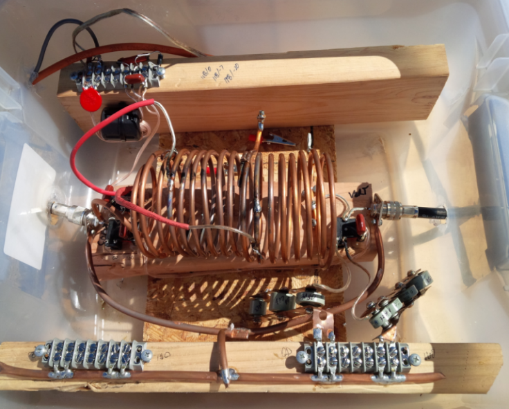
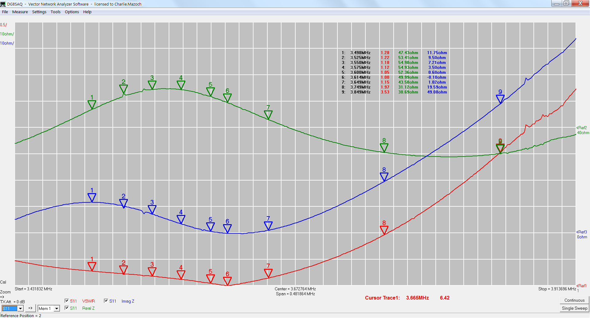
The terminal block at the top left is where the shack band control wire comes in. The line has a MOV clamp and common mode choke, followed by a pi-net to kill off any remaining differential mode RF. A diode clamps the back-EMF from the relays. And a cap across each relay is added for a bit of overkill just to ensure the relays near the inductor don't buzz with any RF the control lines may have picked up. The wires will be taped up where they pass into the box. And a bit of insect "food" will be sprayed on the inside of the tub to discourage any bugs who may find their way in. Weep holes are cut in the bottom just in case water does find a way into the box. While ugly, the L/C net functional and allows very easy change out of components to trim the match. A replacement network built to more proper standards will make a good winter project. SWR and Bandwidth MeasurementsWith the VNA connected to the 2x6 switch end of the RG-11, the SWR and bandwidth results are shown in these two plots. The curves are identical at the shack, although very slightly better due to the small loss from the 300' of additional RG-213 running between the 2x6 switch and the shack. Primary interests on 80m are CW, RTTY and DX - all of which are on the lower end of the band. 80m SWR results: 3.500 1.28 3.550 1.18 3.600 1.05 3.650 1.15 3.750 1.97 Best match of SWR 1.0:1 at 3.614. Click on each plot to see a high-resolution copy. 
160m - interest is primarily CW DX (about 1.820-1.840) and CW contesting (about1.805-1.875). SWR results: 1.800 2.55 1.825 1.48 1.850 1.20 1.875 2.10 The best match was at 1.840 at 1.0:1. 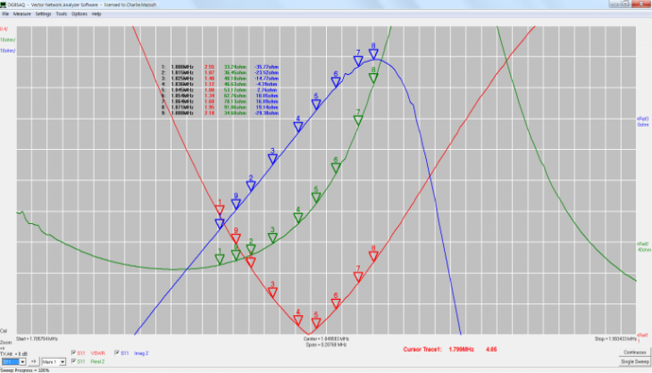
Lowering and Raising the Vertical The vertical can be lowered by one man (and a garden tractor) via a derrick arrangement. 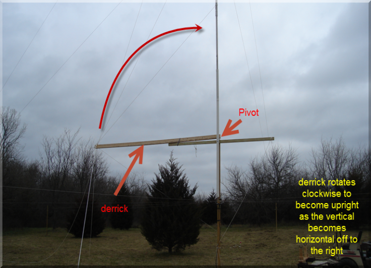
Short video showing the antenna being first lowered, and then raised (MP4 format, 7.2Mb): Download HERE In the video, one of the antennas guy ropes gets caught in a tree when raising it back up - normally the antenna does not bend nearly this much when it's coming up! As it was getting dark when the video was shot, I did not notice the severe bend until I later saw the video. Since then the offending trees have found alternative employment as firewood but the chance of a snag always remains. I think I will try to avoid raising the vertical late in the day in the future, just to not tempt fate too much. Credits I want to thank Greg Ordy W8WWV, Dan Maguire AC6LA and Larry Benko W0QE for their assistance (again) with various technical aspects of the verticals construction. Serious EZNEC users will want to check out Dan's AutoEZ which automates some EZNEC functions and provides an amazing optimization feature. AutoEZ will be guiding me to the final optimization of the vertical as I try to cut remaining losses and maximize SWR bandwidth on 160m. To John Devore ON4UN for writing a great book which first got me interested in topband. And to Rudy Severns N6LF for his exceptional work on elevated radials. AC6LA: www.ac6la.com N6LF: www.antennasbyn6lf.com W8WWV: www.seed-solutions.com/gregordy/Amateur%20Radio/W8WWV%20Experimentation.htm W0QE: www.w0qe.com Things To Do A few things remain on the to-do list... 1. The elevated radial current distribution has not been measured. I can do that with the VNA and the MUX board. Or even with an analog RF current meter (for a rough check). But that's a project for later after I figure out some nice and strong method to anchor the elevated radials at the vertical base. Another idea I had that would not require fancy gear is to setup the radials on a screw block connection scheme so that radials could be connected one-by-one. The thinking here is that I trim the first radial to some frequency. Then disconnect it, and connect the next radial. The radial is trimmed until the resonant frequency reads the same as the first radial. Repeat with all radials. And at the end, connect them all up. I suspect (but have not tested it) that this method should result in identical currents when measured. 2. Some of the ropes used are not the UV Dacron type and the vertical is going to see a longer service life that initially planned. These non-UV resistant ropes need to be changed to the UV resistant types. 3. While the L/C net is functional, it's an amazingly ugly mess. That entire thing needs to be redone. Winter project. 4. Add SO239 to allow connection of coax traps for harmonic suppression. They can be switched by the 80/160 control line. 5. The cap hat wires are not as tight to the guys as they need to be and this causes a bit of extra SWR variation when the wind is blowing. An easy fix, but the vertical needs to be dropped to do that. A little tweak of the L/C will likely be required as a result. 6. There are quite a few parts of the overall match - all of which affect SWR bandwidth and loss to some extent. Fortunately AutoEZ makes evaluation of these much easier than manual work in EZNEC. For example, moving the antenna resonant frequency on 160m (easy to do with cap hat lengths) - or adding a bit more coax length - may reduce the amount of inductance required for the needed match and that will pay off in wider bandwidth and less loss. A lot of exploration awaits investigation here and AutoEZ will guide me the final answers for the next optimization of the vertical. 7. Get proper sized static drain resistors mounted. |