This Antenna "Just Wants to Work" 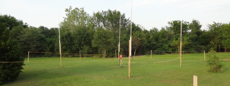
Modeling ResultsThe original elevated radial layout used was very simple. It's a sort of "tic-tac-toe" topology with the 4 verticals at the intersections as shown below. The 8 corner radials were 34' in length; approximately a quarter wave. 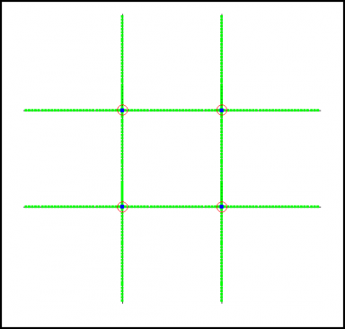
However, as I gave more consideration to the N6LF work in QEX, I wondered if the interconnected layout was in fact a good choice or not. I had concluded from this article that shortened radials would result in far less current variation between the similar-but-not-quite-exactly-the-same radials. Looking at current variations for a 2" short radial suggested that a 10% short radial length would be about right. So the next question was how to orient the radials among the available space. While N6LF has documented the use of elevated radials for individual verticals, there is very little published work on formal evaluations of radial layouts in an array context - at least that I could find. ON4UN has a drawing of a pair of verticals using offset but radials; unfortunately that would not work for a 4-square. Fortunately, EZNEC was some help here. Most of the model variations I worked up had a similar EL/AZ pattern with one provision - that they were not interconnected as I had done. If the verticals are interconnected directly in the model (tic-tac-toe style), then the higher angles of the EL pattern (from 45-120 degrees) showed a higher level of response compared to most variations where the radials remained separate. I view the higher elevation angle response as being bad, and decided from this exercise that I needed to find a radial layout which allowed for radial separation. EL/AZ plots showing the comparison are given lower in the page. Some general principles which I personally believed were desirable included being symmetric around the individual vertical, and additionally being symmetric around the Z-axis. All the variants with 4-radials per vertical failed in one of the symmetry goals, but a nice design which did comply was workable with 3 radials per vertical (as shown below). 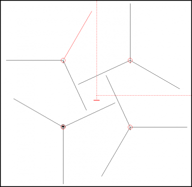
Elevation model of the 30' shortened tri-radial design (with vertical lengths increased to restore resonance at 7.0 Mhz): 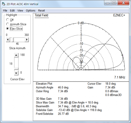
A comparison of the tri-radial design (black) and the old tic-tac-toe design (blue) here. Notice the increased response to signals in the 45-110 degree range by the old design. The new design is less directive (note the -20 db peak off the back-side at about 120 degrees), however, I think this is a reasonable trade-off for a DX antenna given that signals from the most vertical are likly to be NVIS local guys - or atmospheric noise. The new design is about 0.3 dB higher in forward gain compared to the prior tic-tac-toe design. 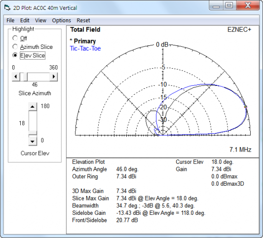
A comparison of the azimuth plots is shown here. Beamwidth is essentially unchanged. 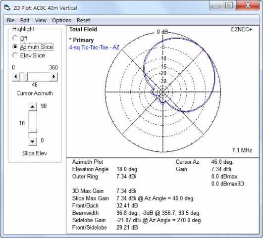
Physical Construction Details Holes for the posts were dug with an auger. And posts were set in the ground with scrap lumber at both the bottom and top. This was done because the location of the 4-square is likly to move as the perminant antenna configuration gets worked out - and pulling these will be a lot easier without concrete. Posts are pressure treated lumber of the "yellow" variety. Radial height varies from about 4' to almost 6' as the ground has a slight tilt. Radial lengths are 30' from the junction to tip, with an accuracy of about 1/2". The aluminum fence wire has a bit of stretch but these wires have been up for the last year and I think have already stretched as much as they will. Radials were supported either directly by a bungie cord connecting the radial end to the post (with zip-ties at the radial end providing a insulator function for these high-voltage points). Ropes between two ajacent posts provided a anchor location for the radials which terminated in the center of the posts. 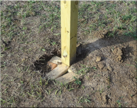 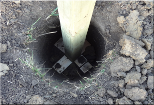
Because the radials were shortened, the length of each vertical needed to be extended to bring the vertical back to resonance on target. However, I did not have long enough stock on hand to accomplish that, so the easy solution was to use some T110-2 powder cores for a slight inductive load. The SO239 are mounted on fiberglass rods; and the rod is screwed to the wood post. The radials are built from aluminum fence wire. The radials for each vertical are buffed and then coated in Pentrox. They are twisted together and a SS wire cable clamp is put over that to keep intimate contact. I don't know if this is a good longer term solution or not, but it does seem to be adequate for at least one year of the Kansas weather cycle. 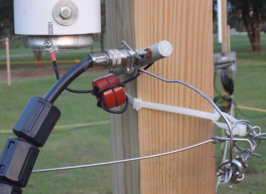
The natural wildlife was also part of the problem providing a temporarly pause in the rebuilding action. When I pulled the covering bucket off the post to gain access to the DXE box, the vermin were quite suprised. 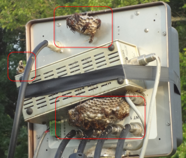
|