 Taking a close look at the XF-126CN filter Taking a close look at the XF-126CN filter
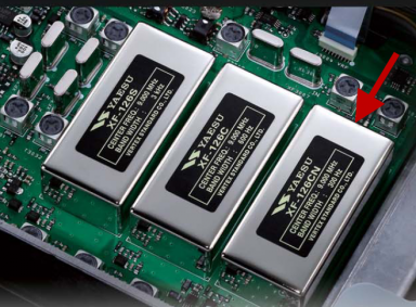
Inquiring minds want to know if the advertised characteristics of this filter match up with the actual performance - and how the important but never publicized value of group delay looks. Bench work was taken from a XF-126CN filter characterized using the veneruable N2PK VNA. Data was confirmed by a 3rd party independent lab - a step taken because the termination of the filter is around 500 ohms in the nominal case and the normal work I do is all close to 50 ohms. It was great to see nearly perfect agreement between the data taken here and that of the professional lab. BackgroundThe FT-5000 is a departure by Yaesu from a string of up-converting architechure rigs to a down-conversion. This move is surely driven by the market's focus on the close-spaced DR3 performance and the technological difficulty/expense of making high-performance VHF narrow filters with acceptable IMD characteristics. The location of the filter is listed in the block diagram shown below. The rig has quite a variety of filters available for the operator's selection. And on the serious selectivity end, a 3 Khz, 600 hz and a 300 hz. The 300 hz filter is what we are considering in this analysis. 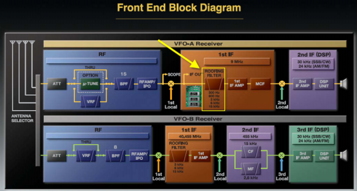
Expectations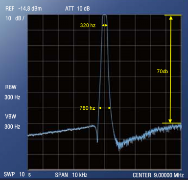
From the Yaesu FT-5000 advertising brochure, we find this plot of the 300 hz filter shown at the right. Note: For proper setting of our expectations, we will consider that the exact test method that the brochure tests is unknown. The notation on the plog "REF -14.8 dbm" suggests that the filter was tested in the radio rather than seperately. So we want to consider if the numbers we deduce from the brochure would make sense or not in our analysis to fowllow. With some magnification and scaling, we can estimate the values of the critical characteristics based on the given span of 1 khz/division horizontal and 10db/division vertical. -6 db bandwidth: 320 hz -60 db bandwidth: 780 hz Attenuation floor: -70dbc From this we can calculate the shape factor at 2.44. Insertion loss is not specified but a typical 6-pole 9 Mhz design would run in the 3-6db range. These numbers do seem to make sense for a filter advertised as being "300 hz" in width. And so for the rest of the evaluation, we can make the assumption that whatever the test method used by Yaesu, our filter-only comparison to this data would be a reasonable compare. Bench Test Results Note: Because the filter has a non-standard termination of about 500 ohms, I used 16db minimum loss pads to handle the z transform. Calculations were pulled from the chemandy.com page on-line tool which was very handy for this kind of thing and works great in practice. Looking at the attenuation floor of the filter, the first of the Yaesu claims can be put to the test. Here we see a roughly 70db gap between the filter passband and the filter floor. 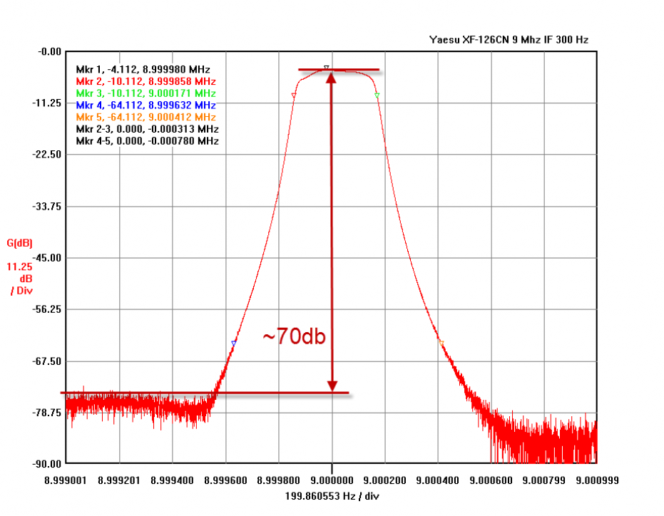
Next, zooming in a bit and letting the VNA take a more detailed look, we can see how the N2PK finds the filter's key metrics: Measured -6 db bandwidth: 313 hz (blue arrow) Measured -60 db bandwidth: 779 hz (green arrow) Calculated shape factor from the measured 6/60 point is 2.49. Finally, the measured insertion loss is about 4.1 db (red arrow). Again here on the core metrics, we find very good performance and very good agreement with the published data and bench findings. 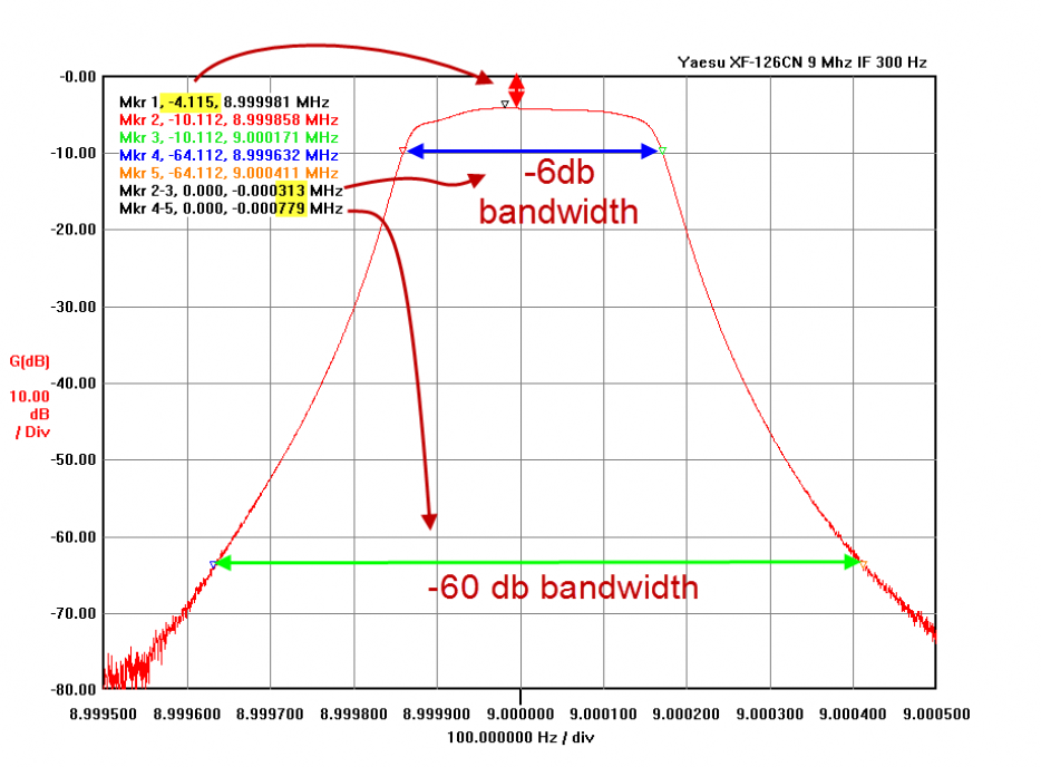
Looking closely at the top 10 db or so of the passband, we see a very nice overall shape . The very slight variations seen here are all negligable and are a combination of the filter's actual performance as well as very minor possible mismatches in the termination or test plate. All well within what we would expect to see considering the measurement methods used. 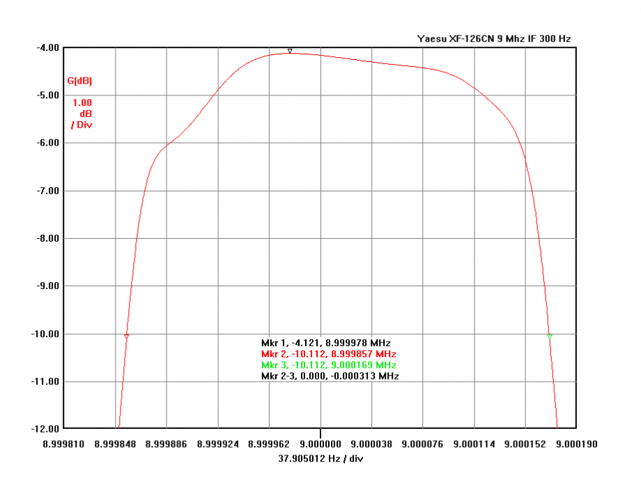
Group DelayFinally, taking a look at group delay, we find a value of 4.5 mS change from the center of the passband to the maximum. Change in the group delay over frequency is the technical term for expressing what we as operators experience as ringing. The faster the rate of change in the group delay, the more noticable the ringing is. Variations in group delay come as a trade-off with increased selectivity. I'm not suggesting the observed group delay as necessarly good or bad. Rather, pointing out this effect as an example of what we ops hear when using narrow filters. A signal of any strength centered in the passband against a QRN-free band is going to sound nice and clear. How we may notice the effects of these "ears" in the group delay plot on either side is on a night were wide-band QRN is present and you are trying to pick up a signal that is at the noise level. The group delay characteristic may tend to make the band noise present near the top and bottom of the passband ring more and it may in the worst case prevent you from hearing the signal in the center of the passband. Notice that I have said "may" and "tend" here - that's because different ops are sensitive to ringing in different ways and to differing levels. A given level of ringing may or may not be a consideration for you. However, if you have a rig (of any manufacture) with a narrow filter that you do find fatiguing to use after a period of operation, it's quite possible you are feeling the subsconscious effects of ringing as your brain works hard to provide the extra descrimination between the weak signal and ajacent ringing content within the AF delivered to your ears. What can be done to minimize the effect? Under these circumstances, use of the rig's DSP filtering at a 200 hz or so width should cut off this edge ringing. Most newer rig implementations have a pretty flat group delay characteristic and this is one case where the combination of the rig's roof and the DSP can work together to provide results that each alone is not capabile of. And of course, if band conditions allow, using a 600 hz filter selection will improve the copy because the frequency location of the group delay peaks will be further seperated from the signal, assuming it's centered in the passband. 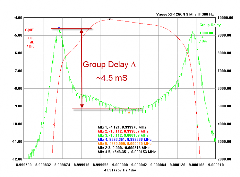
ConclusionsBased on the bench test results, the filter works as advertised matching the published brochure data almost exactly. And as a roofing filter, it's performance is excellent in the metrics that matter most - the top end of the attenuation plot and in low insertion loss. And as a side benefit, the selectivity vs. group delay tradeoff is a nice balance. |