Station Automation combined with an Intuitive User Interface 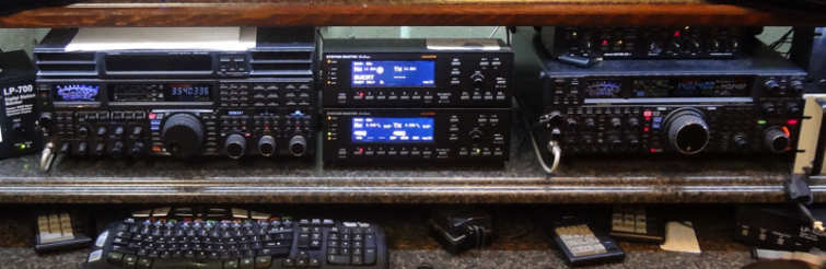
The Station Master Deluxe (SMD) system is a series of network-connected control boxes and a user interface. This page expands on the user interface. The switching hardware end is covered on the Skynet Control page here. The SMD connects into the rig's CAT and PTT lines and coordinates the switching of antennas and other frequency-dependent boxes in the shack like BPF. It also can control amp selection and some other station hardware. That means there is no separate antenna switch in my shack - all the antenna control is through the SMD. Even the DXE 4-square controllers and the HiZ 8-circle controller boxes are replaced by the SMD. SMD vs. SMThe SMD differs in two fundamental ways from the Station Master which I used in the prior station build for years. First, the number of relays controlled by the SM is limited to 20 where the SMD allows attachment of a nearly unlimited set of modules - which include relays, serial interfaces and rotor controllers. And secondly all of the stuff tied into the Microham modules is treated as a "shared" resource meaning it can be controlled by any of the SMD. The SM by comparison is hard-wired to a given rig and that means the hardware must be built to accept two sets of independent hardware controls (as is the case with a 2x6 switch, etc). How to Drive the SMD Box As So2r is the primary contest mode here, I have stuck the SMD interface boxes between my two rigs for ease of reach. 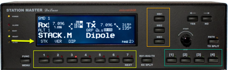
A close up of the SMD box is shown above. The graphic display shows which antennas have been selected - with full support for split mode operation (meaning RX and TX modes are using different antennas). The 7 buttons along the bottom (yellow box) allow direct selection to antennas. In this stock photo they have a stack, a vert and a dipole as the options. To select an antenna, just push the button 1-2-3 to get what you want. Settings are band-specific meaning a move to another band, then return back will restore the last selected antenna configuration automatically. The set of buttons in the green box are used for predefined quick direction access. For example, should you have a 4-square selected as the antenna (via yellow box button press), then you push one of the 4 buttons to set a direction. Press any 2 buttons and the DXE 4-square OMNI direction is selected. What I am not yet sure of but think is likely is that the same sort of thing can be applied to stack combos. Meaning I can designate Button [1] as being "ROT+FIXED EU" for example. Part of the setup let's you tie that action to the relay combo resulting in the box giving me the proper setting for the 7 stack control lines that would yield a stack combo of ROT+FIXED EU. Or I could designate it as "ROT" and then button 2 as "FIXED on EU" with the physical button press combo of 1+2. Slice the bread as you like apparently! Slick. The SMD also ties into the serial feed of the Green Heron controllers allowing the beam direction to be shown on the SMD graphic display. And beam direction can be set by the rotary knob or with a button push. Receiving-only antennas can be selected in the same way after pressing the "RX SPLIT" button to tell the SMD you want to assign different antennas to RX and TX modes. This is how I operate on 160m for example. The TX antenna is the 160m full size vertical and the RX antenna is a choice of the HiZ circle, the NE-pointing beverage, the skimmer all-band short vertical or even the 160m vertical. The orange box let's you store a group of 3 "combo" settings where the entire configuration at a given time is memorized and assigned to a button. That makes it handy to return the SMD to some known initial configuration with one button press. Let's say your primary use is no RX antenna, 4SQ pointed on NE - that setup could be assigned to MB1. In the heat of the action maybe you went to a dipole trying to work a guy in Nebraska and used the RX array because of QRN or whatever. Instead picking the 4SQ, then setting the direction, then turning off the split RX antenna - you just push the MB1 to "get back home." 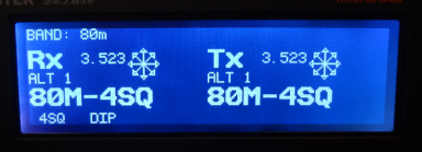
The SMD has plenty of eye candy. An example is the "OMNI" graphical representation below (the snowflake looking thing). 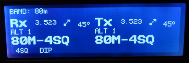
And here's the individual direction representation. Shows a graphic plus a heading. Antenna Selection in StacksThe Monostacker stack matching box supports 4 antennas and offers 9 combinations as follows: 1. Top antenna 2. 2nd down antenna 3. 3rd down antenna 4. Bottom antenna 5. All 4 Antennas 6. Top 3 Antennas 7. Bottom 3 Antennas 8. Top 2 Antennas 9. Middle 2 Antennas Here's an example of how it would work using the 20m antennas for this case: - The physical beam layout on the 20m tower is 3 beams total - one beam up top that is rotating, one fixed on EU and one fixed on SA.
- The stack positions are assigned TOP: rotating, 2nd: fixed on EU, 3rd: fixed on SA. The 4th position is unused.
In this case the stack options would have these meanings with respect to antennas 1. ROTATING (top) 2. FIXED EU (2nd down) 3. FIXED SA (3rd down) 4. <unused> (bottom) 5. <unused> (all 4 selected) 6. ALL 3 (top 3) 7. <unused> (bottom 3) 8. EU Stack (assumes rotating beam pointed to EU) (top 2) 9. Fixed on SA + Fixed on EU split (both SA and EU at same time) (middle 2) Depending on which stack is in use, several of these options will not be available as none of the bands here have a true 4-high stack. However another benefit of the Monostacker is the ability to beam in multiple directions at once. Using the same 20m example, and starting at a bit before dawn, we may start with stack option 8 which has the fixed-on-EU plus rotating selected. We start with the rotating pointed at JA and this let's us beam both Asia and EU as we are waiting for the band to open to EU. Once EU starts to open, we spin the top beam to EU and run into the afternoon. Jumping to option 6 (EU stack + SA) from time to time let's us run with the low beam also in the stack to work SA. If we are having trouble catching the SA guy, option 3 puts all the power into that beam. Later in the afternoon when Asia opens a bit before sunset, we may want to spin the top beam around to Asia and use option 6 to sweep up some SA guys, catch a few Asia mults and keep running EU. The system provides the flexibility and it's up to the operator to get the most out of it. 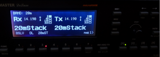
Graphically this is how the stack looks on the SMD - in this case configured with a set of 4 antennas in a stack as top (rotating) beaming N, 2nd beam fixed on EU, 3rd beam on SA and 4th beam on JA. Here the top beam is selected. The up-arrow indicates a N-beam direction. 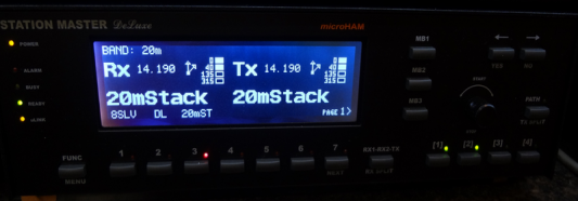
In this example the top 2 beams are selected. Beaming N+NE based on the arrows. If the top beam were pointing NE as well then the two arrows merge into a single arrow. That's the normal graphic for a 2-high stack. 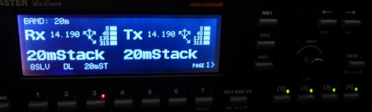
And in this case all 4 of the antennas are selected simultaneously - with the 4 directions represented by the 4 individual arrows. ConfigurationThe box's operation is almost fully user-definable through the Microham configuration utility uROUTER. The granularity of control is excellent including being able to assign switching delays between changes in the antenna state as you move from TX/RX and from band to band, for example. Handling Special CasesA side benefit of the system is that generating a relay control signal for some special case circumstances is very easy. For example the beverage runs very close to the 80m 4-square array and when beaming the SW direction coupled power into the beverage can exceed the input limit of the beverage preamp. So I have a line that drops in some attenuation to the beverage line ahead of the preamp - but only when the 80m 4-square is being used, in the SW direction, and the attached rig is in TX mode. A similar control line protects the skimmer vertical from overload with the 40m 4-square when it's beaming NW and in transmit mode. All together there are perhaps 6 special case configuration exceptions all handled by a bit of software configuration and then tying into one of the unused Microham relay lines. |