Containing Wire Clutter - and More 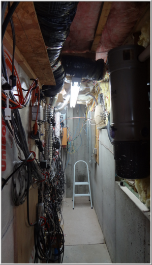
I never found a good way to handle the mess of wires that is part of every ham shack. So the shack is built with the back of the equipment tables extending into an adjoining closet/walk-space. The closet serves the several functions mentioned below. The idea to stick the gear through the wall came from a shack I saw on the Internet. The gentlemen had a lot of gear built into the walls of a larger room. That really seemed a great idea because it solved the 3 major problems of most ham shacks - heat removal, containing wire clutter and sound isolation from gear fans. Wish I could remember the shack owner - it was very impressive. Wires and More WiresWire is grouped when possible in a set of hangars (red hooks in the photos). These run the length of the room on two levels vertically. Closet-mounted gear is attached to bits of plywood connected to the wall. Gear is held to the plywood with wood screws which allow for quick rearrangement when needed. In the latest shack rebuild, much of the RF wiring was replaced with small hardline which has the benefit of being essentially leak-less, important in So2r operation. It also looks great! 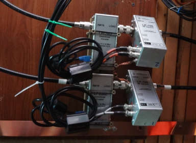
Microham Station Master Deluxe Control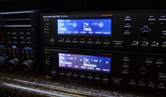 The Skynet reference comes from the station automation which is implemented using the Microham Station Master Deluxe hardware. The Skynet reference comes from the station automation which is implemented using the Microham Station Master Deluxe hardware.
The system consists of a user control panel (located at the operation position - show right) and a set of network-connected switching boxes shown here (with the red numerical LEDs shown below). An additional layer of isolation between the outside world and the shack is provided by the relay boards (blue and red colored strips above the Microham boxes). The isolation relays are not required for the Microham system but they provide very cheap insurance should a lucky lightning strike get through the outside MOV suppressors. 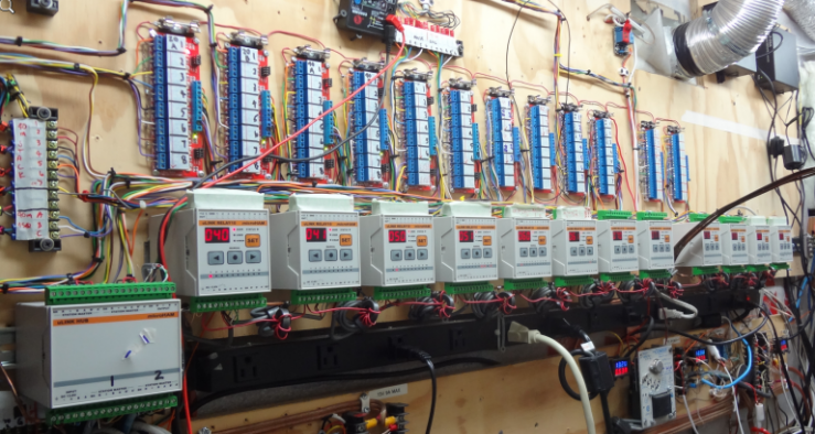
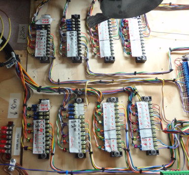
The isolation relay boards are in turn connected to the breakout terminal strips (below right) from the approximately 100 control wires running to the outside world. Ten of the Microham modules are relay drivers (10 relays per module) and the remaining two modules are rotor interfaces which allow the Microham user interface to read rotor position as well as set rotor direction through an external serial connection between the module and the Green Heron rotor controllers. 
Dedicated Shack PC 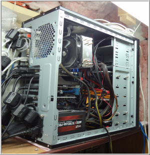 Shack PC is based on the Intel i5-2500 CPU on an Asus motherboard running Windows 7 x32. Shack PC is based on the Intel i5-2500 CPU on an Asus motherboard running Windows 7 x32.
Boot drive and ham apps run off of a OCZ SSD. Secondary storage is 4-250GB drives running RAID 1+0. The trio of Hanns-G 28" 1900x1200 HD monitors is driven by an EVGA 650 Ti Nvidia based graphics card. An Infrasonic Quartet 192 Khz card and Asus provide a total of 1x 192 Khz + 4x 96 Khz low noise inputs for the pair of LP-PAN SDR. A PCI-E card provides 4 serial ports. All lines in/out of the PC have ferrites to cut down on RFI. And the OCZ power supply is pretty quiet both in audible noise and RFI generation. RX Antenna Switching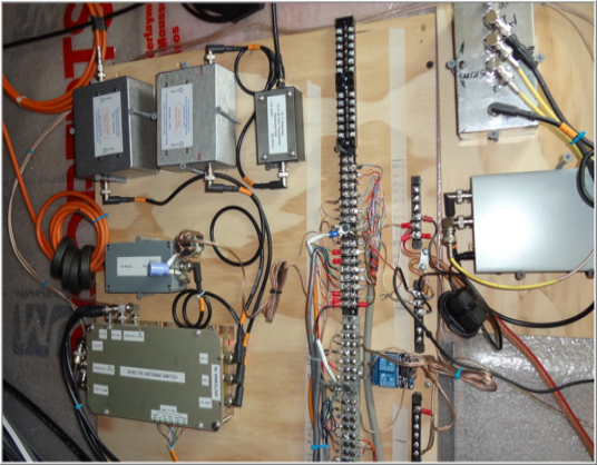
The receiving antennas feed coax comes from the shack termination entryway to this board. Shown here are the K8ZOA HPF for the beverage and Hi-Z circle array and the bias tee for the voltage fed wide-band vertical. The terminal strip on the right is the break-out block for the antenna connections. From the shack, for example the Microham Stationmaster and 4-square control lines come here first. From the outside, the KK1L switch, the 4-square lines from the antenna, etc. Getting all these wires together on the single series of break-out blocks allows for quick and easy changes in antenna switching. RX Antenna Switching BoxIndividual RX antenna selection is managed by the larger box on the bottom left. The RX switching system sets in the rig’s RX antenna loop. The rig forwards the TX antenna to an “RX OUT” – and the RX is fed by the “RX IN” connectors located on the back of the rig. When no RX antenna is selected, the RX OUT and RX IN are connected so no further intervention on the rig is required. The operation logic for each of the antenna selections case is:
- No RX antenna selected: TX antenna used for RX, and the skimmer vertical is connected to the QS1R
- BEV, HiZ or skimmer vertical selected: selected antenna is routed to both the rig and the QS1R
 The output of the box feeds a K8ZOA Clifton Labs Z1043S preamp. The preamp has a stratospheric OIP2 of > +100 dBm and OIP3 of +50 dBm. Gain is about 11 dB. The output of the box feeds a K8ZOA Clifton Labs Z1043S preamp. The preamp has a stratospheric OIP2 of > +100 dBm and OIP3 of +50 dBm. Gain is about 11 dB.
The preamp feeds into a Mini-Circuits 4-way splitter. There is one additional splitter inside the RX switching box which provides isolation between the QS1R and the shack rigs. The splitters ensure individual rig and antenna isolation. 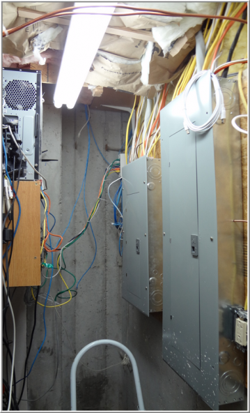
RX antenna selection is driven by the Microham Stationmaster. Antennas can be selected by the SM’s front panel directly – or by an attached keypad which I find to be the most convenient. The keypad is located in the shack right next to the keyboard and paddle. Power - AC and DC AC PowerOn the back wall of the wire closet are the breaker boxes. The house has 400A service total split into two breaker boxes (shown right). The shack has dedicated breakers for each of the two amps as well as lighting, shack general purpose outlets and for the few 4-gang boxes which support direct connection inside the wire closet. Long multi-tap power strips run the length of the table below. And there is one more along the top for gear setting on the top-most shelf of the rack. A total of three 240V @ 30A outlets are installed along both sides of the shack dividing wall with the closet. An additional 240V outlet is mounted on the workbench (adjacent to the shack). DC PowerTaking a queue from K9YC, all the switching PS in the shack have been eliminated leaving only the shack PC. Power comes from a trio of commercial linear power supplies mounted near the closet floor. The supplies are rated at +14.5V @ 9A, +28V @ 10A and 12V @ 9A - all on a 100% duty cycle basis. Actual voltages can be fine tuned via trimpots on the supplies. The 14.5V supply voltage is helpful for the antenna switching wires - being a bit high to help offset the line losses related to the long runs out to the antenna relays. The 12V supply feeds the 5V regulator for the QS1R as well as the desk LED lighting lines. 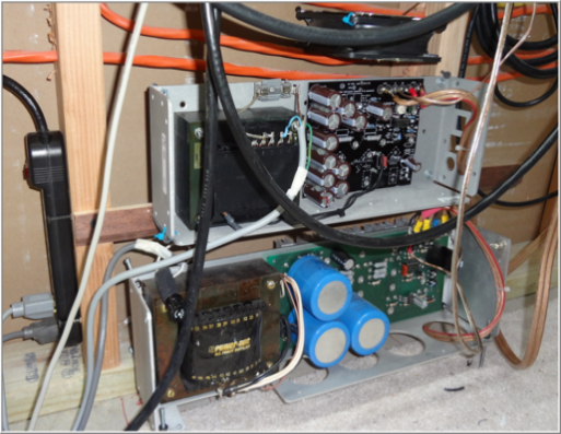
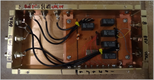
A set of screw-type terminal strips are mounted on a long board just above the equipment opening. #10 wire runs from the supplies up to the terminal strips. The +14V supply metering mounted on the right end of the board. Each supply has a digital dual volt/amp meter monitoring the individual lines. 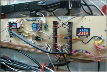 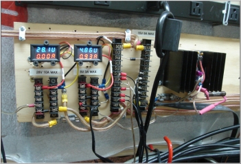
An additional set of +14V terminals are mounted on the left end of the board, along with a set for +28V. The +5V required by the QS1R comes from a dedicated 3-terminal regulator; the heat sink is visible below. A series dropping resistor offloads the heat dissipation from this regulator and keeps things cool. The switching supply sold with the QS1R was quite a noise source and the regulated supply is a big improvement. All 3 supply lines feature a simple crow-bar type of over voltage protection circuit composed of a series fuse and big TVS diode mounted on the terminal strip. In the event voltage rises above a safety level, the TVS conducts and causes the fuse to blow. Need to keep that QS1R and other gear safe from PS and (more likely human) failures! |