
Fitting It All InI did not realize just how limited the space under the chassis was until I started to try to fit everything needed into the space available. The rough fit of the various modules resulted in nearly every available space of the chassis being used. The current module placement is shown here: 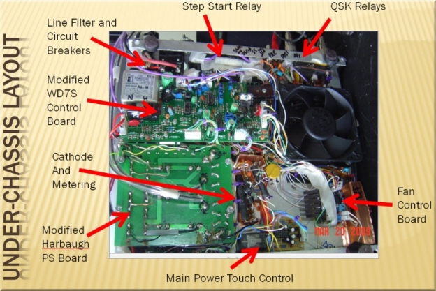
Brians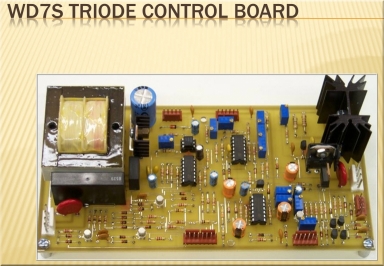
Before I was RTTY-crazy, I was CW-crazy. And having played with full break-in QSK, I wanted to ensure the new amp had the capability to support this feature. While it's possible to build your own circuitry for controlling the various amp's functions and providing protection, there are two boards on the market that make this a comparative easy project. GM3SEK has a board which provides the similar features as the WD7S offering with a couple of differences. The WD7S board provides explicit support for QSK, it has an LED output for each of the various fault conditions, and the board is physically smaller. It was for those reasons that I opted to use the WD7S board. A complete set of the WD7S TCB features is shown below. 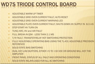
The board functions as advertised and the documentation is adequate for the advanced builder. In my case, there was not enough clearance for the bias circuit's heat sink or the transformer so both of those functions have been moved off board. The part of the PCB where the transformer is designed to be located has been cut out in my amp to allow for the AC line filter. Some jumpers were added to the board to work around the missing part of the PCB. 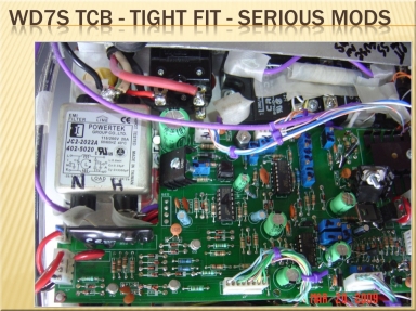
I recall a few errors on the part placement diagram which took a while to figure out - wish I had recorded those so that I could save other builders the trouble. Overall I'm pleased with the board. I had contacted WD7S on a few questions which he was kind enough to reply and even took the time to share a short telephone call with me. However, it is clear that his support is really setup for the more advanced builder. For a first time amp builder, especially someone who may be looking for more of a plug-and-play solution, I would strongly recommend the GM3SEK board simply because the documentation is excellent for that board compared to the more minimal nature that the WD7S board provides. Of course, others experiences may have been different than mine. The front panel of the amp has been "augmented" with LEDs to take full advantage of the WD7S board's fault indication. This is not required - but I'm a big fan of having a lot of lights, switches and knobs on my equipment - so bringing out all the LEDs to the front panel was a necessity. :) 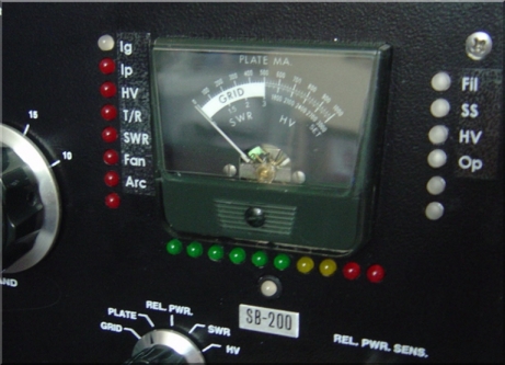
T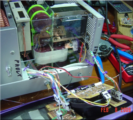 A couple of the LEDs remain unassigned. Fault functions are aligned on the left - with the grid LED having a dual-color mode (yellow warning, red for fault). The right side of the panel is all blue in color. So in "normal" operation, the right side LEDs will all be blue and the left side will be unlit. The LED above the SB-200 label is the enable (green)/standby (blue) /transmit (red) tri-color LED. Labeling was done with a Brother label maker - many color options are available including white on clear which was the chice for this project. Build advice - determine in advance what the LED intensity level should be for your projets. I had not considered this initially and found that the intensity levels set on the bench (against a brightly lit workspace) were entirely too bright when moved over to the shack bench. The new high-intensity blue LED are especially "eye catching." Shown below (left) is the backside of the amp instrumentation. At the top of the picture is the LM3914 bar graph board. The board is held in place by velcro allowing easy removal of the board and does not require additional screws to be put into the faceplate. The left and right small boards hold the amp fault and status LED and are also removable. And at center is the meter backlight board. Take note of the huge diodes over the meter - replacement meter movements are hard to find for these old amps and a couple of back-to-back beefy diodes prevents just about any kind of damage that could possibly be applied. See more comments on this subject further down the page. 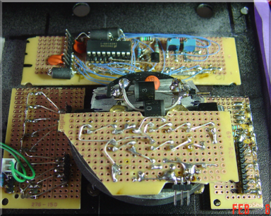
Meter Backlight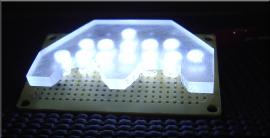
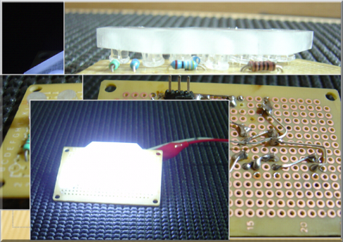
The module mounted to the back side of the front panel multi-function analog meter is a white backlight source. I could not find a "light bar" of the proper dimensions and constructed this one instead. The LEDs are filed flat and countersunk into the plastic. A "fog" colored pain was applied to provide further diffusion of the light. The cutouts allow the meter to sit over the terminals and just above the production diodes. A foam surround wraps over the top of the meter to increase the contrast by suppressing light that would project upward through the top of the case. The overall visual result is excellent. 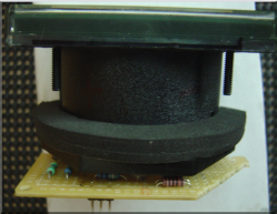
Soft Power / Standby Switch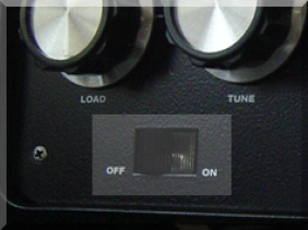
I wanted to preserve as much as possible the classic theme of the amp but when it came to adding a standby switch, I was at a loss. Eventually I settled on this solution... 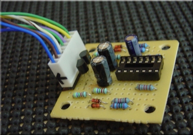 The original toggle power switch was replaced with a center-off, dual directional toggle of the similar apearance. The original toggle power switch was replaced with a center-off, dual directional toggle of the similar apearance.
Pushing the switch to the left (toward the OFF lettering) toggles the amp master power. Pushing the switch to the right (toward the ON lettering) toggles the standby/enable circuit. A simple circuit based on a NE556 handles the switching and debounce. And this allows the amount of time to be preset before a switch is recognized as being pushed. For example, to turn the amp power on, the switch must be pushed about 5 seconds before it's activated - preventing any inadvertent power on. On the other hand, to turn the power off requires pressing the button only about 1 second. A similar logic applies to the enable/standby function. QSK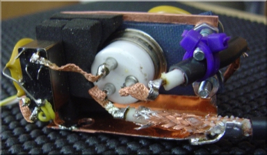
The QSK feature implemented in the WD7S system follows a similar design style as Richard Measures speed-up overvoltage circuit. I've not tested the circuit but WD7S has documentation on his web site showing effective speeds of only a few mS. The mounting shown here with the foam is part of my attemps to deaden the sound. The vaccum relay is quite loud and is suspended by the foam block - held at each end by the copper frame. Sound can also be transmitted along the interconnecting wires hence the use of the copper braid. Wires were kept as short as possible. The connection from the amp-out to the So239 is made with RG-8X. I've had zero problems with this implementation and is very quiet in operation. I beleive with the chassis case on the unit, the relay may be unaudiable even with the fan at idle speeds. Input Matching NetThe input match is provided by pi-networks. The excellent PI-EL program helped to get me into the right ballpark. And then the L/C values were fine-tuned for best overall amp efficiency and input match. The relay at the right switches the 80m bandswitch wafer segment between the 80m and 160m input match net. I chose the toroids over the stock network because I observed excessive heating in the L/C which I beleive is related to excessive Q. It was easier in the end just to put in the toroids which seem to be very robust and don't heat at all even under sustained key down. It is interesting to note that the input matching net has a HUGE effect on amp efficiency - up to perhaps 15% in some cases - far beyond what I can explain. What is puzzling is that the input matching network's impact on amp efficiency is far more sensitive than the actual match to the rig. It was easy to get a good SWR match to the rig, but the trick was fine tuning the input for both max efficiency of the amp and a good match to the rig at the same time. My advice to any Gi7b amp builder - be sure to allocate time to adjusting the input matching network looking not only at the input match but also on the amp efficiency. It's time well spent. When I later replace the tank, I will be able to bring a more scientific approach to this input matching as I have a VNA now and the MFJ259 is repaired from "somehow" getting the input diodes blown :) Should be interesting! 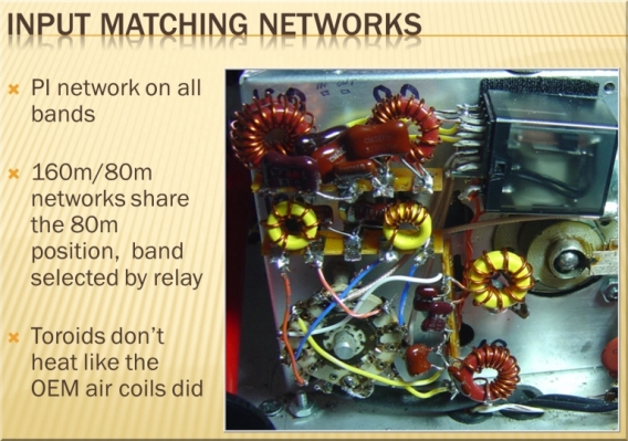
Major Items Remaining:The amp has performed well in 3 RTTY contests so far. And I'm confident the overall design is sound. But there remains a lot of work remaining before this project can be considered "complete." - Mount the new plate transformer and clean up the existing power supply circuitry
- Replace the various bits of stand-alone logic with an AVR-based micro controller - this is a step back from the "simple is better" philosophy but in my case, a microcontrolled board will have far less parts and can be fortified against RFI ingress than the existing bits and pieces of circuitry now used
- Replace the current tank configuration (shared 40/80m toroid) into dedicated seperate toroids for 80/160m. 40m and above will be copper. The current design shares 40m with the 80m toroid and that results in localized heating of the toroid to levels I am not comfortable with. The efficiency on 40m is lacking as well suggesting the tank has excessive loss. Higher bands are of more interest now that the cycle is improving and this is a chance to clean up the Q for all the bands in one operation. I have a leakage tester now so this should be simpler than the last time I worked on the tank - because of the tight spaces in there, arcing is a problem and a leakage tester is a good way to find it - much better than hunting it down with a full powered amp!
But then again - is an amplifier project really ever "fully complete?" ============================================================================================================== The School of Hard Knocks - A Couple of Important Lessons Learned The high voltages exposed in an amplifier can kill you. But for some people at lesson seems a hard one to learn. I got two lessons for free, to help remind me of the dangers. I'm much more cautious now. And very thankful that the amp and my body survived both lessons... Lesson 1 - protection diodes are NOT optional A dozen or so diodes applied at the right point in the amp can save a lot of hardware from distruction. And if you are going to put in a diode, use a big one - meaning one that has a high surge current rating. You just never know what kind of accidents or trouble waits down the road. For example, let's say you are probing the high voltage line searching for the source of why one of the filter caps keeps exploding. And for some reason you have been too lazy to actually cut the lead to the bleeder resistor so you can measure it seperately. You instead have been clipping on bleeder resistors thinking if the original bleeder is open, this would fix the probem. And then, oops, the clip comes off one end of the cap and falls - down - onto - the - analog - meter. What are the odds of that? Happened to me. Fortunately I had put the insurance (back-to-back diodes) onto the back of the meter and other than some momentary fireworks, no damage was done.  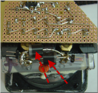
Lesson 2 - Make sure the power supply is really off and bleed down fully before proceeding I'm not sure what I was doing that day. Not paying attention, most certainly. Managed to stick my finger between the B+ line at the input side of the plate choke and the input side of the pi network. Enough current flowed between those two points to blow both the amp's breakers and pop the HV fuse indicating a full discharge of the filter caps through my fingertip. The skin was charred slightly in 2 spots but otherwise, no damage done. Be careful where you put your fingers... 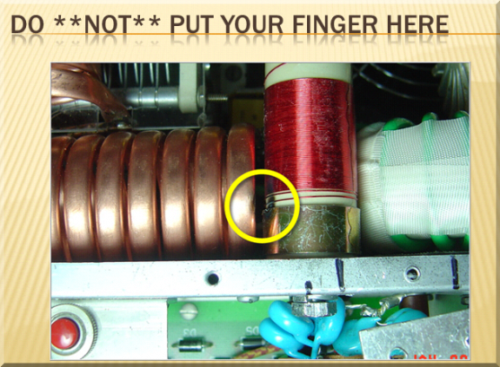
|