
PART 3 - Starting Over Starting with the stock RF deck - with glitch fuse and muffen mounted 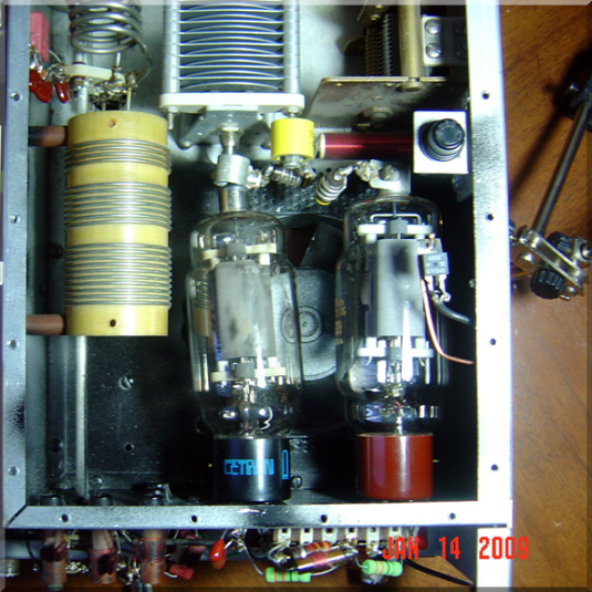
Fitting the plate chokeThe plate choke is from Ameritron. It reads about 200 uH total and is split to avoid in-band resonances. The biggest challange was trying to figure out where to put it! 
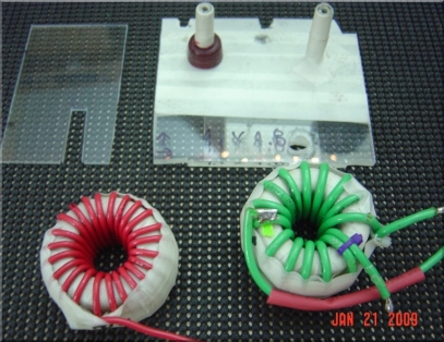
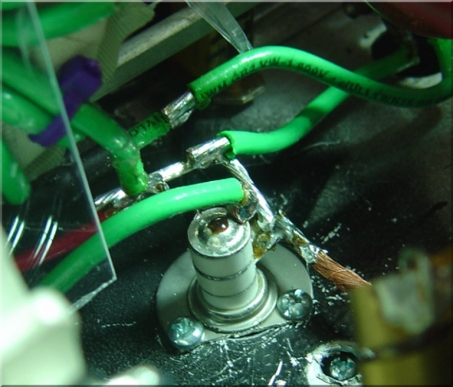
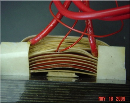
Toroids for 40/80/160mThe 160m (red winding) is dedicated for 160m. And the green winding is for 40/80m. The mounts allow a good fit to ceramic standoffs. And the high-temp teflon tape helps to give a bit of heat protection to the soft PS and keeps the toroids tightly fit on the standoffs. The balance of the tank is implemented in copper. Performance on 20m and 80m is exceptional. Other bands good and poor on 40m. The Q is in the 8-10 range on all bands - and I suspect the shared ferrite is the problem on 40m. And the Q is in fact higher than 8-10 on the higher bands due to the stray cap (higher C means lower L and the ratio relates to the tank's Q). 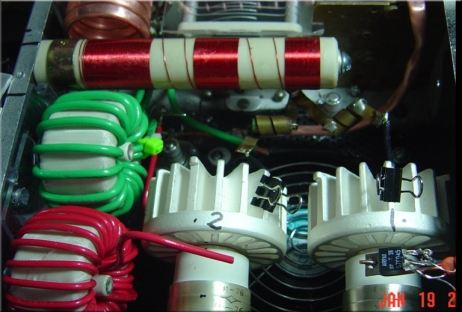
160m load pads and relay switching (left) and 160m inductor shorting relay (right). The circuitry for this follows the R. Measures modification but it's pretty simple to follow. A relay on the input side adds a pad to the input. And on the output, a cap is switched in and the red toroid is added to the circuit (shorted on other bands). A seperate relay on the input matching side switches between a 80m pi and 160m pi net (see input circuit photos lower on this page). Control for the relays is via a front panen push-switch which is part of the old SWR sensitivity switch. An LED located near the 80m label on the bandswitch indicates 160m mode is engaged. 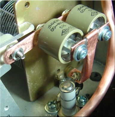
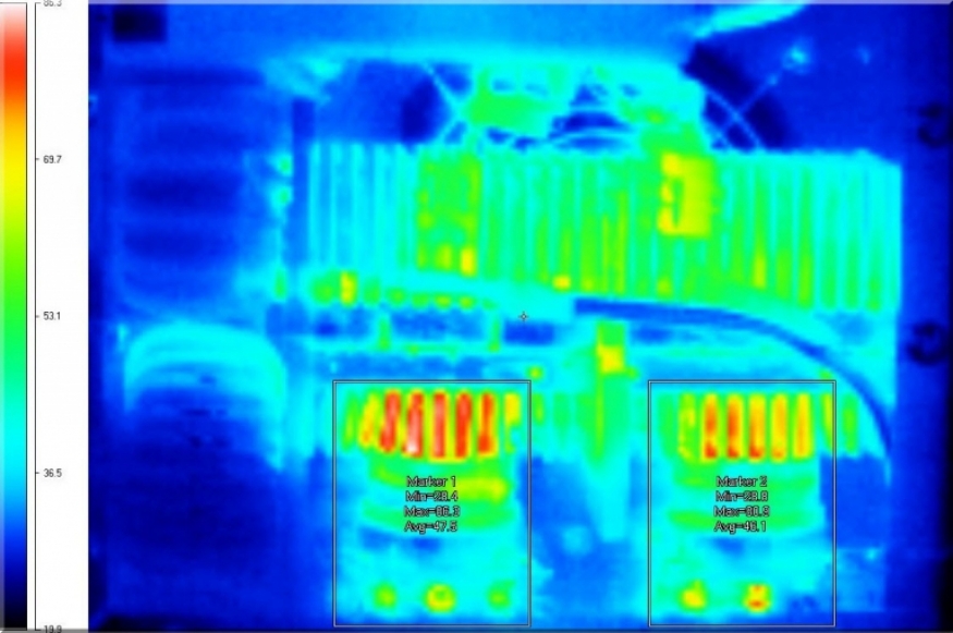
Custom Anode Cooling 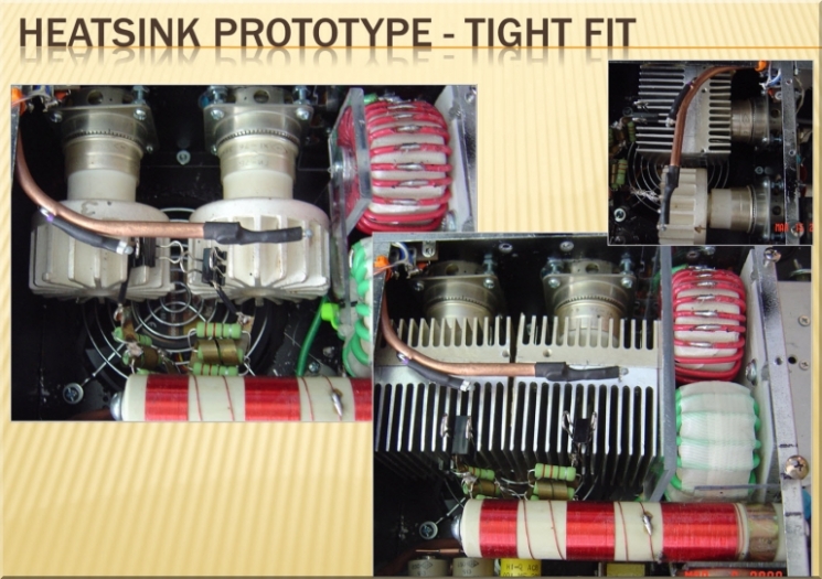
By far the most cool test gadget I have ever used is the IR camera. It provides James Bond style heat signature pictures, along with a very specific temperature reading at every point in the photo. In this picutre we can see the enlarged heat sinks are keeping the tubes much cooler - almost 80C lower. A very valuable benefit of this is that it was the first point where I noticed that the toroid on 40m was heating significantly. Subsequent checking showed temps over 100C. 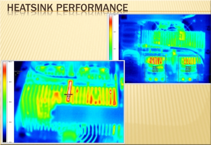
Keeping Cool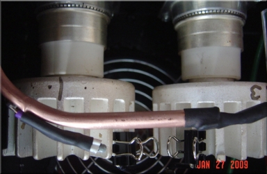
A friend of mine showed me the Acom 2000 - wow, what a nice amp. One of the very best features is that the cooling fans are nearly silent. And the volume of air/noise produced ramps smoothly with the cooling demands. I thought that was wonderful and it's also one of the project goals. I don't mind an amp that makes some noise when it's huffing/puffing and blowing the RTTY houses down. But at idle, who wants to hear an amp fan? Not me. The solution was to put a variable speed fan of some kind. The final solution was to use a IC specific to the purpose. The circuitry is pretty simple but because all inputs/outputs need to be RF bypassed, the complexity and board size increases a bit. Temperature is sensed directly above the hot spot of each tube via theristors. One for each tube, in parallel. With the two sensors in parallel the warmer of the two tubes tends to set the fan speed. Given the somewhat offset position of the muffen fan with respect to the cooling fin layout, the tube on the right tends to run warmer than the tube on the right. The fan circuit is active regardless of the power soft-switch which allows the fans to keep running until the cut out temp is reached. The operator does not need to wait for the fan to cool down before hitting the power off switch. I have tried several fans in this position including a 300 cfm 24V unit that is just fantastically powerful. However the noise profile of that fan, even at low speeds, is pretty loud. In the final version, I will probably end up using about a 200 cfm unit as that seems about the best overall compromise between low idle noise and capable high speed volume performance. A small sister module built from a LM3814 sits on the back of the front panel providing bar-graph LED indication of temperature. This module takes it's input voltage sense level from the varistors as well and provides a convenient front panel indication of realitive temperature. By adjusting the slope and offset of the LM3914 input, I can have the bar graph correspond to actual temperature warning levels if needed. This combination works fine in it's current implementation. However, I plan now to replace all of these individual seperate modules with a small MCU module based on the Atmel AVR. That would give me much more control over the "personality" of the amplifier and result in a far less complicated circuit implementation. This is counter to traditional amp design philosophy - but for my case, the weak spot is not the semiconductors used, but rather the number of fragile interconnections . 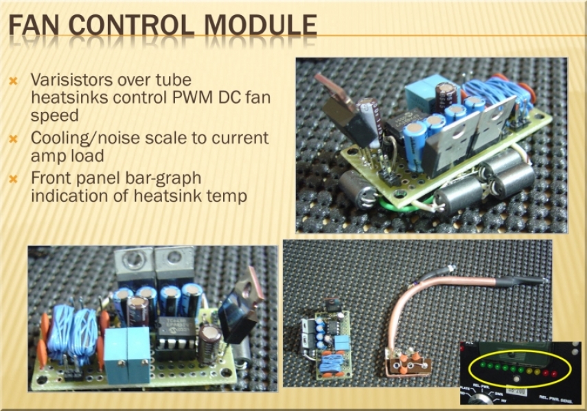
Power Supply ModuleShown here are the filament and key-down hour meters - the vertical beige boxes visible in these pictures. The black transformer here is the filament unit. Located behind the filament transformer is the DC transformer for the low voltage circuitry and fan circuit. 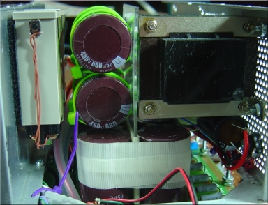
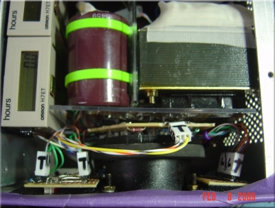
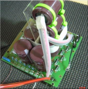
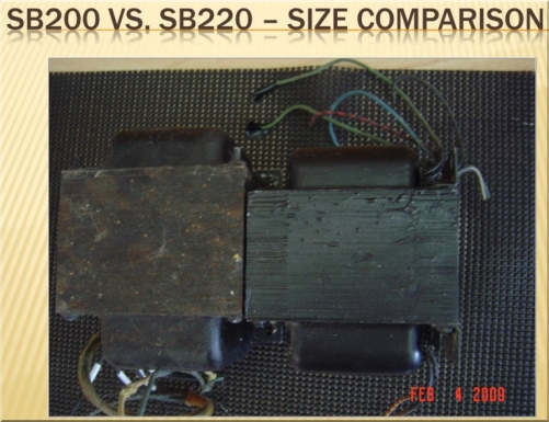
The power supply module is fully removable (picture at right). HV runs are insulated with plastic piping. The original design of the Harbaugh board supported 6 caps but given the higher voltages this amp runs at, a total of 8 450v caps is used. 0.1% 3W precision bleeders are put across each cap to help keep the cap voltage values even. Transformer Replacement - Plan AInitially, the target Sleeper transformer was going to be the SB220. It's slightly larger in size and has quite a big higher B+ idle voltage (2500 vs. 3100v). The stock SB200 transformer was very sturdy and showed only minimal heating in the difficult bench testing done prior to moving to this transformer. Hopes were high that we would be able to get the similar performance at a higher voltage from this SB220 transformer. 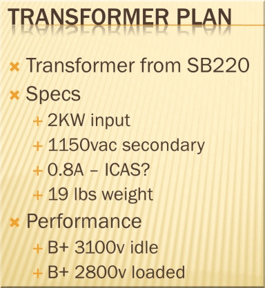
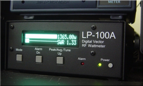
The voltage ran 3100v at idle pushing the calibrated voltmeter on the SB200 nearly to the peg. And that resulted in quite a nice showing as the LP-100 picture shows. Clearly with a larger power supply, meeting our target power (1KW @ RTTY service) will be easy to achieve. 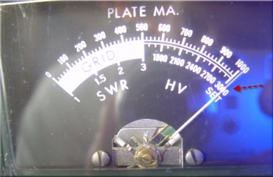
Unfortunately, the luck was not going to hold. After about 15 minutes of intermittemnt testing on various bands, a catestrophic failure occured. 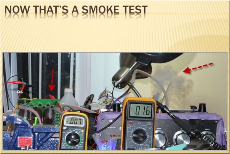
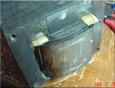
Investigation was traced to a crispy transformer. The transfomer had not been used in years and so it's impossible to know the actual failure mode root cause. However, as I found out later, the SB220 is not known for having an industrial duty power supply... Quite a bit of collatorale damage - step start resistors, few others. Quite a mess... Clearly a stronger transformer is needed. And the solution came in the form of a loan from Alex KU1CW. 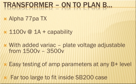
I did not have handy a 220v variac so I tied the 120v variac into one side of the power line. This allowed varying the B+ level applied to the SB200 to range from about 1800-3200v. A fan over the variac was added just for good measure. The Alpha 77ap transformer on the other hand needed no cooling. That is a MASSIVE transformer weighing about 45 lbs. 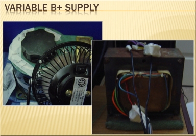
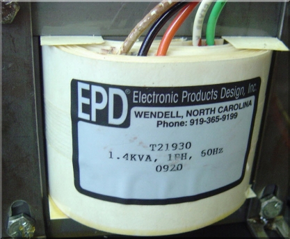
After a lot of testing of the SB200 at various voltages, I decided that a custom transformer would be the ideal solution. Eventually I found Peter Eggimann at Electronic Product Designs. Peter immediately understood the problem and was very helpful in finding the solution. Working with Peter over the span of a couple of weeks, a design came together that looked very good toward the target specifications. The amount of power that is demanded from the amp is about 1.4KW at RTTY cycle. That cooresponds to a sustained 0.7A output level from the doubler at voltage ranges of 2300-2900V idle. All the objectives of the design were realized. And EPD was even able to embed a thermistor between the primary and seconadary which opens the door to real-time monitoring of the transformers INTERNAL temperature. Measuring the external temp of the transformer is posssible but due to the high thermal mass of the iron structure, it takes a long time to get a reading at all - and that reading is much different than the actual internal transformer temperature. 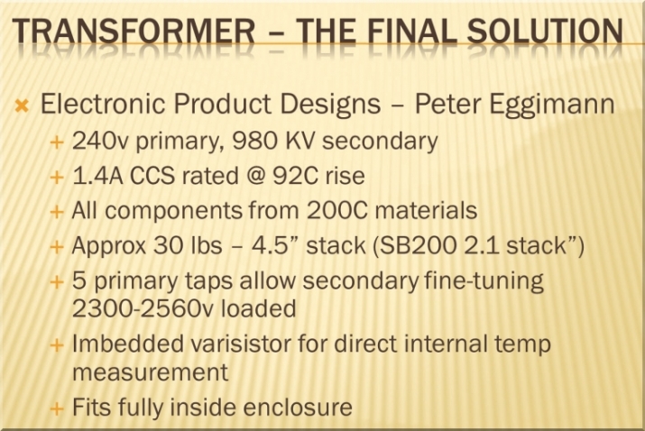
Comparison of the stock SB200 vs. the EPD unit. 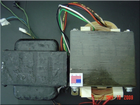
The thermistor (left below) is rated at 300C max. It's very tiny. The thermistor is routed out of the transistor via these 2 small red wires. 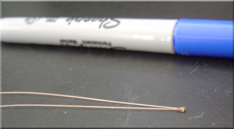
 
|