Kicking Antenna-to-Antenna So2r Isolation Up a Notch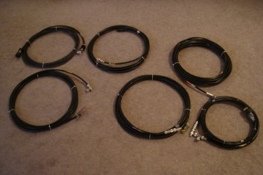 After completing the Gen 5 array and taking the initial antenna-to-antenna coupling measurements, it was time to cook up a series of coax stubs. The stubs design and construction are detailed below. Improvement in antenna-to-antenna isolation due to the addition of the stubs is found HERE. The stubs are part of an overall set of techniques used to isolate the two rigs antennas. In most cases, a single stub has been added. But these things are iterative. Build, measure, use, and then consider "is that enough?" If it's not, additional stubs can be added in a cascade network to provide more attenuation. For each of the stub sets, the Elsie model and the VNA scan of the actual stub set is shown. Although the Elsie models assume ideal zero-loss coax elements, the agreement is close between modeled and measured performance. Because of the ideal coax in the Elsie models, they show huge attenuation at the null point - when in reality, a single physical stub will offer attenuation in the 22-28 db range. Coax Stubs for 40m Antenna Operation
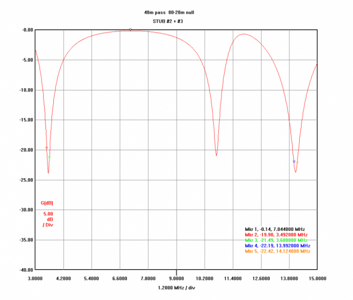
The 40m antenna stub set is composed of two stubs - one for 80 and one for 20. 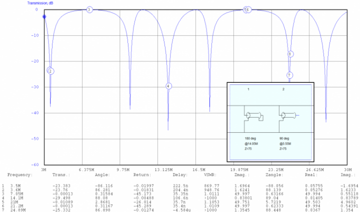
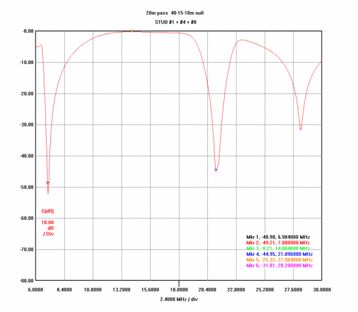
Coax Stubs for 20m Antenna Operation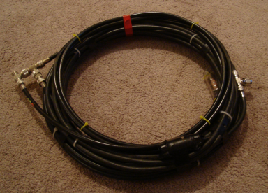
The 20m antenna has the most complex stub set. Individual stubs tuned for 40 and 15 are separated by a 5-foot section of RG-213. And on one end, a 10m notch has been added. This combo allows the normal adjacent band suppression for 20/40 and 20/15 operation. And with the 10m notch, 20/10m is enhanced as well. The 20/10m So2r combination was not anticipated in the original Gen 5 design - but given the tepid sunspot activity, running on 20 with one rig - and jumping between 15/10 on the other - seems a more likely need hence the added 20m stub. 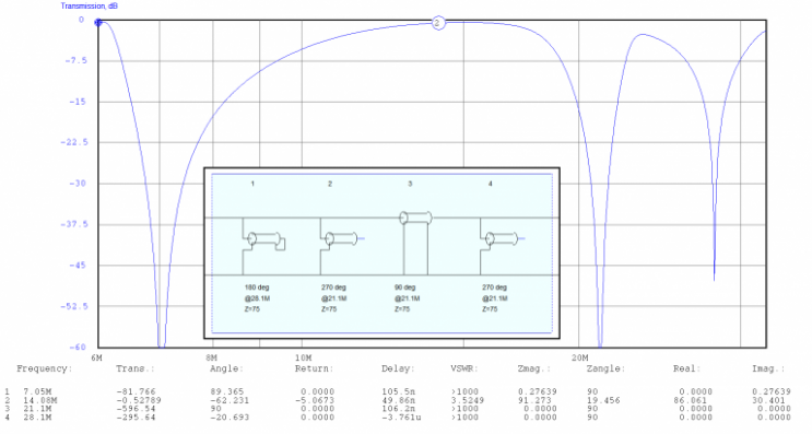
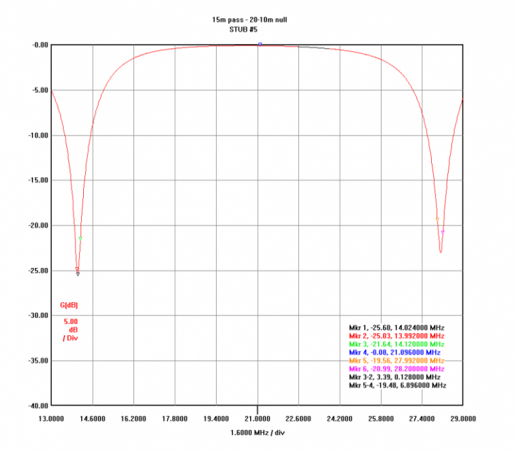
Coax Stubs for 15m Antenna Operation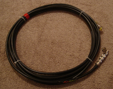
The 15m antenna uses a single stub which provides notching for 20m and 10m. The 15m DE also serves as the 17m antenna and so the stub performance at 18.1 MHz was of interest. Using 75 ohm coax, both the model and VNA estimated about 0.35 dB of loss which is a very nice result as well. This stub was inadvertently trimmed a bit high in frequency (too short). And visible here, on the lower coax tee, are an additional set of M-M and F-F couplers which together serve to slightly lower the resonant frequency. 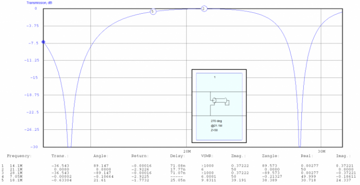
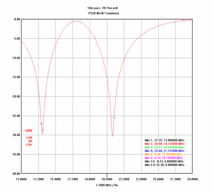
Coax Stubs for 10m Antenna Operation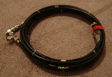
The 10m antenna stub set is a combination of 20m and 15m stubs directly connected. 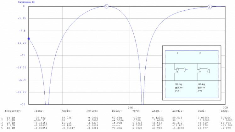
|