20m is the anchor band when we have a rising sunspot condition. When things are cooking, propagation-wise, the band can be open over the entire 24 hour period. So it's worth taking a look at this beam and making sure the latest-and-greatest in attic knowledge has been applied to this key band. Design ChangesAs with the 10m/15m beams, the 20m has been converted to a 2-element variety with a bit tighter spacing. The east-director is now in the same vertical plane as the 40m and 10m east-most beam elements. This allows for a very clean east-bound radiation pattern but it does place a premium on decoupling. Another complication was the So2r consideration. As with the higher bands, the simplifying assumption has been made that operation on 20m will be conducted under So2r in conjunction with 40m or 15m operation only. 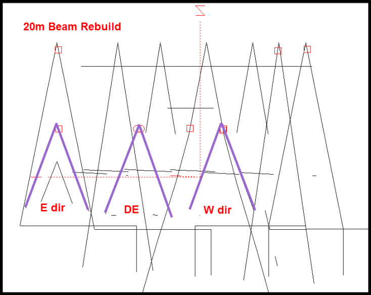
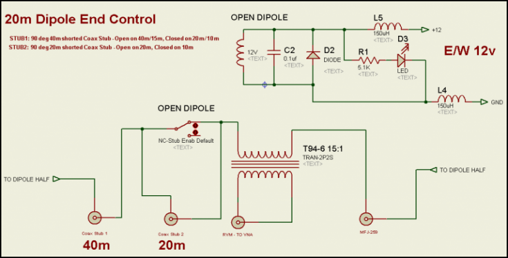
The EZNEC model calls for a director switching matrix which operates this way: 40m: don't care 20m: Closed or open - as needed for directional control 15m: Open always 10m: Closed always This combination is realized with two stubs and a relay and functions in this manner... - The first stub, a 40m closed 1/4 wave type, ensures the 40m and 15m band energy (present in So2r operation with 15m or 40m) sees the element as an open at all times. The stub is also a short on 20m, and when wired in series with a relay tied to the E/W line, we have the open/short action needed for the direction switching function.
- On 10m the elements need to be closed and the 40m stub provides that. However, because it's wired in series with the relay, on 10m the element appears as either open or shorted, depending on the relay setting. To solve this, we have a 20m closed 1/4 wave type wired in parallel with the relay.
- This second stub functions as an open on 20m (allowing the relay to provide the 20m open/short for direction control), and it serves as a short on 10m at all times.
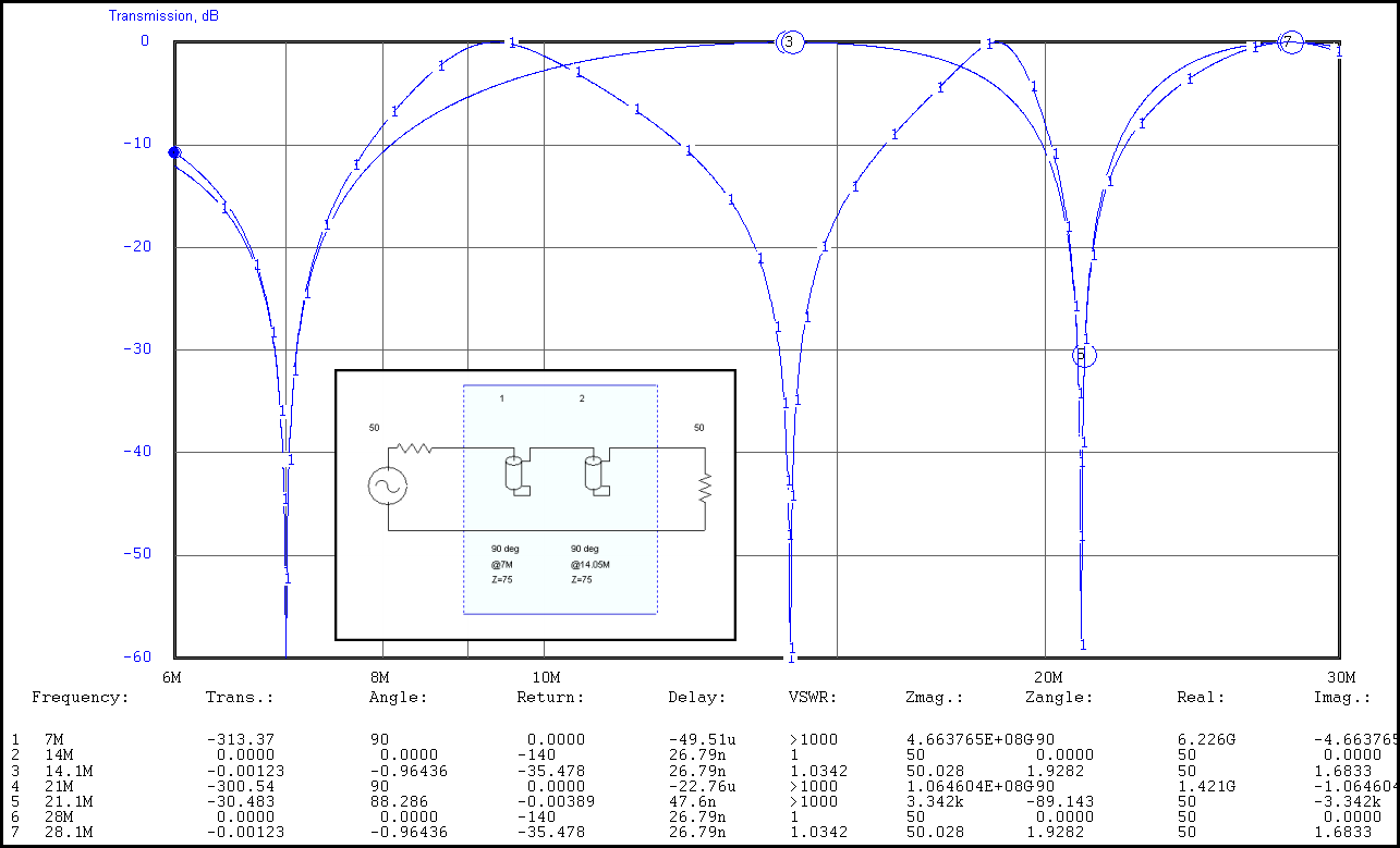
The graph below shows the action of the two stubs in series with the relay OPEN (dashed-1-line). The solid line shows the action with the relay CLOSED. Notice that 40m/15m are open in both positions - and the 10m is closed in both positions. Finally, 20m is either open or shorted, depending on the relay setting. Click the graph for a higher-resolution view. 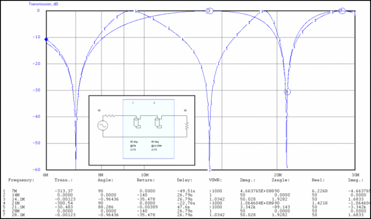
Models The east beaming direction has a clean model. However, the director has no obstructions in front of it so that would be expected. 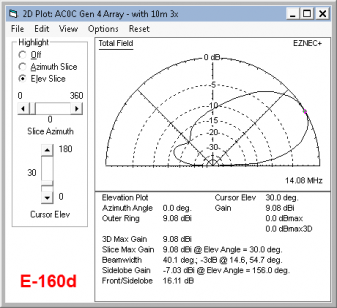 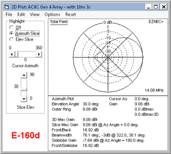
But for the west beaming pattern, it's not as nice. The F/B is going to be under 10db based on the current model. I will have to take another look at this later to see if it can be improved. 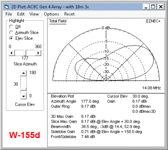 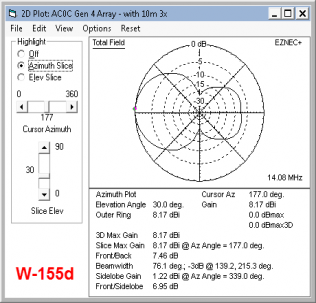
Build DetailsConstruction is similar to the 10m and 15m prior works. Key components shown below. [The switching board is an earlier rev, and not shown are the 20m stubs which were added as a design improvement.] 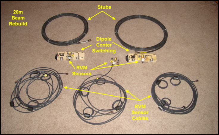
And for the center of each director, the dipole switching board looks like this. Notice the relay is in series with the stub for the 20m design. 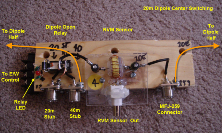
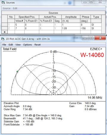
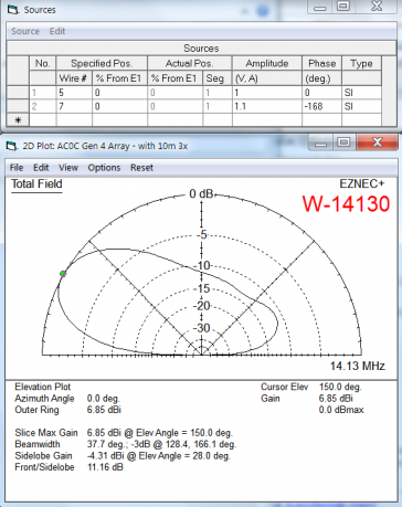
ResultsMeasured current magnitude and phases from the RVM sensors, and then used as sources in the model, provide the following predections of actual antenna pattern. Freq 20m EAST 20m WEST ------------ --------------------- ------------------- 14.100 0.87 -146 deg 1.04 -145 14.060 0.87 -154 1.09 -156 14.130 0.84 -163 1.10 -168 With some diddling, I ended up with this set of measurements. The target phase should be closer to 160 deg but as the phase goes up, the bandwidth really goes down (as well as the feedpoint R). At 155, it was around 13-20 ohms already. So I left it at 155-ish to see.how it works out. 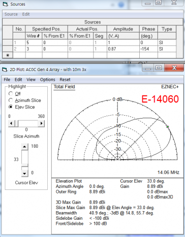 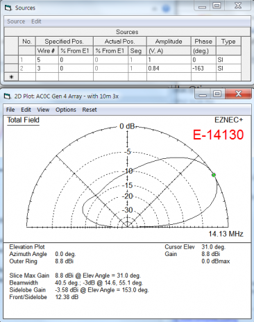
Things To Fix Later1. The F/B and gain on west-beaming side suffers compared to the east beaming direction |