Updating the power supply The original design for the power supply element of the attic switching relay board was built around the assumption of about 1/2 A total power demand. And as the antenna system has take shape over the last year, especially with the phased 40m array, the power demand has increased dramatically. Leaving the existing power supply operating well beyond design norms. Add attic temps which may reach 60C+ in the summer time, and you have a problem just waiting to happen. Of course, a power supply failure would result in a non-functional antenna system. Not good. If Mr. Murphy were to get his way, the failure would come about 2 hours into a favorite contest run. Now that is terrible!!! Better fix that power supply problem... That turned out to be a bigger challenge than I had expected. The Old Supply The old supply was built around a 1A 36V w/CT transformer feeding a FWBR. The two secondary windings of the CT transformer were wired in parallel giving a 2A 18V AC supply into the bridge. It was bypassed on both sides with caps and both the input and output sides were fused. Safe and quiet, the PS provides around 24-28V depending on load. Fine for the 24V relays I have used for most of the new attic additions. As the load demand on the power supply has went up, the undersized and shared heat sink (lower yellow box) ran hot enough to burn your finger. I did not measure the sink's temp - and had just hoped for the best. Fixing it was going to be quite a project - and with the array untested and unproven at that point, it was a problem for the "let's fix that later" category. To help cut down a bit on the power dissipated by the linear 3-terminal regulators, I did put a small power resistor in series with the 12V regulator input lead . Not ideal; but given the load was primarily relays (not so picky on regulated supply quality) so it was functional - and in retrospect, I'm sure it's contributed to the units 2-year (so far) track record of solid performance. 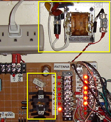
The New Supply The SO2R conversion means more power-hungry relays. So I knew it was well past time for a power supply update. No more excuses to delay. And fortunately, at Dayton this year, a vendor was selling 24V 4.5A switching power supplies. I originally had no intention of using a switching supply but had found some to be quiet enough. And hoped this unit would be the same... I started out by using my poor man's spectrum analyzer for the test. I run coax into the antenna input of the rig and put a loop of wire between the center and the shield of the coax to serve as a pick-up loop. The pickup loop is moved around the box - or wound around the cables - and then I look at the 192 KHz spectrum of the PowerSDR display. Power is applied to this supply, and I look for a change in the noise floor on the display - as well as spikes. My assumption is that the loop in immediate contact with the power supply is a much more sensitive test than the full sized attic antenna. The test is repeated for each ham band. It's tedious but it does provide a workable way to test gadgets like this power supply where RF radiation is something you want to check out. If the unit under test is generating noise, then I apply whatever kind of bypassing or filtering I think will work and repeat the test. Fortunately, for this supply, it was very quiet on all bands. The 24V output is wrapped several times through a big type 31 ferrite (bottom right of the pic below) and an additional 0.1 uF cap is stuck right at the output pins. 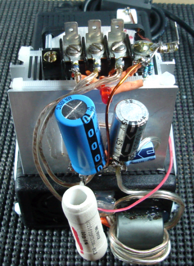
To replace the old supply, the new one needs to deliver 24, 12 and 5V. However, given the higher currents and prior heat problem, I mounted the new regulators on a big computer CPU heat sink. And in the junkbox a small fan was fitted to the heat sink. A huge improvement in the thermal mass of the prior heat sink arrangement. The old 1A 7812 regulator is replaced in this design with the LD1084 5A adjustable 3-terminal type. It's trimmed to provide about 13.75V. The input resistor in this case is a big 10-ohm 25W wire wound type. And finally the 5V 7805 which primarily drives some logic chips has been changed for a 7806 6-volt regulator. I'm sure the 5 volt nominal CMOS chips will work fine at 6V instead of 5V, and the added 1V will give a bit more noise guardband. 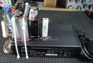
The 12V fan is hooked to the 24V line via the power resistor you see to the right of the fan. This keeps a pretty significant static drain out of the 12V line heat sink load. Between each of the regulators, the usual assortment of tantalum and electrolytic caps have been added. And a LED is added as well on the 5V line to give a visual indication of power - something I wish I had added on more of the control and signal lines in this project! The supply won't be disturbed once mounted so not much attenuation was given to physical protection to the exposed low voltage circuitry. The terminal block along the top makes the unit somewhat modular and facilitates easy removal if future service would be needed. 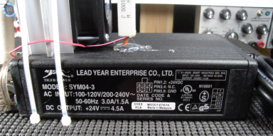
On the to-do list is adding fuse protection for each of the lines (I may do that with self-resetting fuses) and of course, adding fuses to the AC side. Installation location will need to be worked out once I'm up in the attic but I think at this point it may be on the back-side of the current relay board. |