A Short Explanation of the Decoupling Design The stubs and relays work together to minimize the currents picked up by elements that are not part of the current antenna in operation. The complexity of the system is driven by this requirement. To the extent that decoupling can be optimized, the other wires/elements in the array will appear to not exist for a given band. Likewise, the currents in the other elements that are not eliminated will serve to influence the pattern, most commonly impacting the F/B ratio. When So2r is considered, two bands with two antennas are operating at one time making the decoupling task more complicated. In many cases what provides minimum current pickup for a given element on one band, is not the same setting for another band. If these two bands are part of the So2r operation range, the stubs and relays must work together to provide the magic that makes a given element appear open in one band, and closed in another. Relays serve to open or short elements in the center - which doubles/halves the effective wire length and providing control over the resonant frequency of each element in the array. However, relays are frequency independent. In the many case where an best relay settings were (for example) open on one band, and closed on the second band, stubs are then used to provide the "switching." The longer the element, the more bands it may influence - in fact, the 160/80m dipole element has 3 relay break points along the length in addition to two sets of stubs. The steps to determine the needed relay settings followed this process:
- Determine best element location within the array based on EZNEC analysis - looking for least interaction with other elements - and least pattern distortion
- Within the model, consider the currents of each element in the array. For those elements, try both the center point open and short to determine the best fit.
- If the antenna is part of the 5 major So2r bands (80-10), then do the currents analysis on each adjacent band.
- If the decoupling setting (either open or short) is the same for both the adjacent band So2r case, then a relay can be used.
- If the decoupling setting is different, then a stub combination is needed. Here, Elsie software was used to confirm design ideas for the stubs.
The spreadsheet below provides an insight into the various combinations required. Generally speaking, the array is mostly decoupled through stubs now for the So2r contest bands. And hard-decoupled via relay on the WARC bands. More specifics for the stub/relay combination used is covered under each of the individual antennas in the tabs to the left. 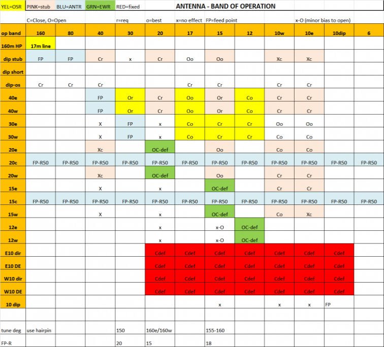
|