This presentation details the work of converting the 40m 2-element reversible beam into a phase-driven type of array done in late 2010. 40m Parasitic Drive Highlights Operational diagram of the array shown here. The half wave lengths serve to duplicate the feed points of the two elements and help to avoid a lot of attic climbing! The phasing method uses a variation of the Christman method, as explained by Lewallen. Because the east and west elements cannot be made to look identical in R/X, separate phasing lines are switched in depending on the direction (east or west beaming). The phasing switch box also supports a in-phase "OMNI" mode which is a great help in the normally nulled areas of south and north. 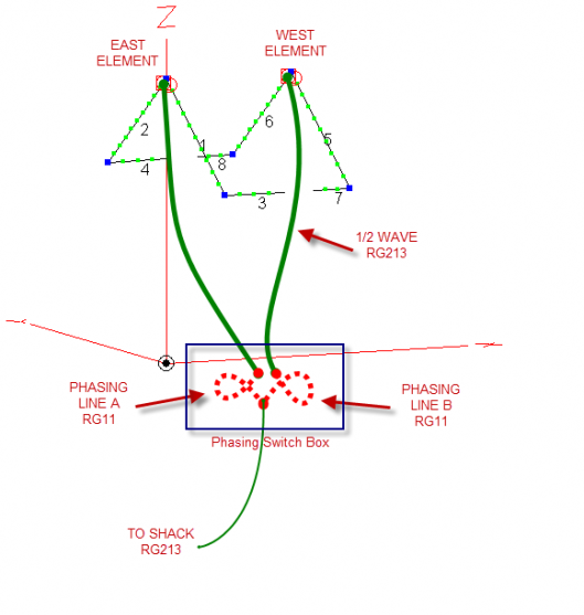
The steps to implementing a Christman Phasing array are shown here: 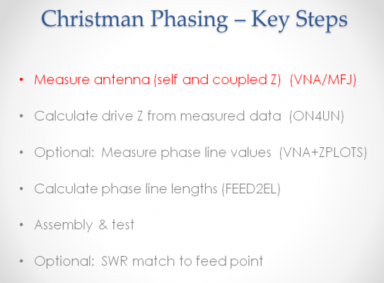
Using Dan Maguire's Feedline Master spreadsheet tool FEED2EL, the lengths can be determined very precisely including the option to use measured VP and loss values. Thanks Dan for another great tool! 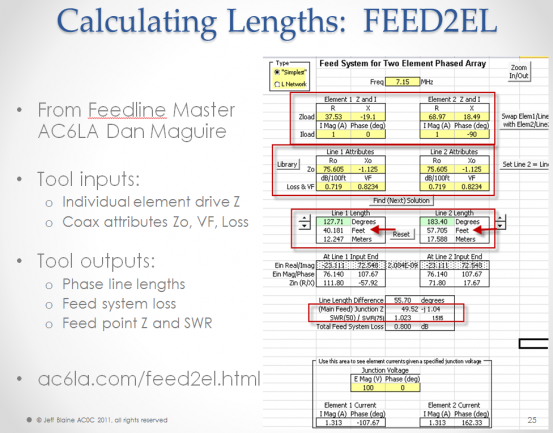
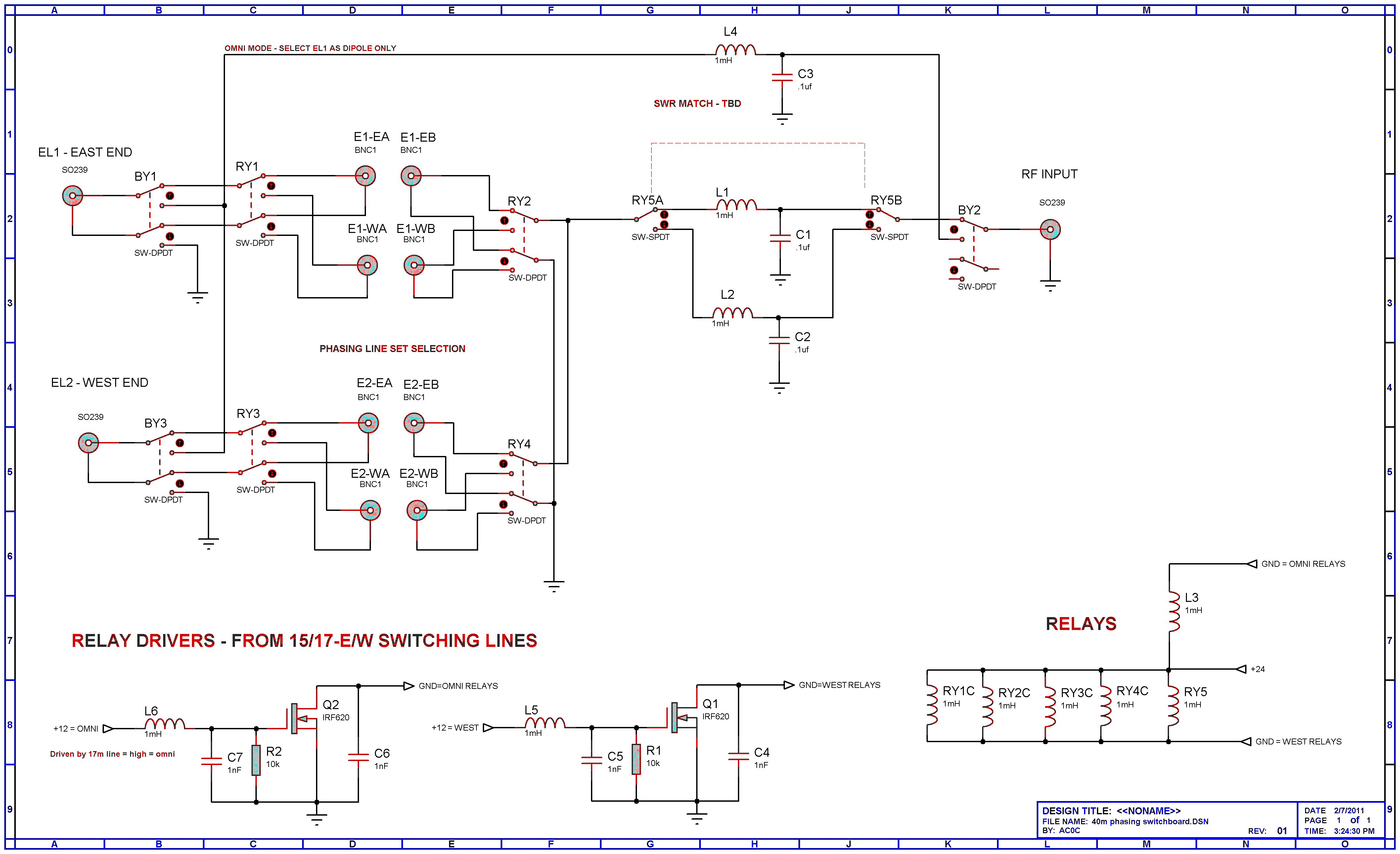
Schematic of the switching system shown here. Click schematic for a high resolution version. 
Phase line switching system is built from a wood reinforced Plexiglas frame. This is helpful because most of the So239 connectors are insulated from each other. The board accommodates two sets of lines - the second set is planned for use with the current 30m fixed-east parasitic antenna. 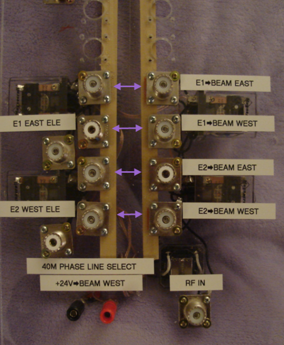
Relay connections are point to point. To offset the series inductance, caps were inserted on each of the feed lines - values selected based on VNA measurements. Each of the relays are cap bypassed and diode clamped to keep RF out of the relay control lines. 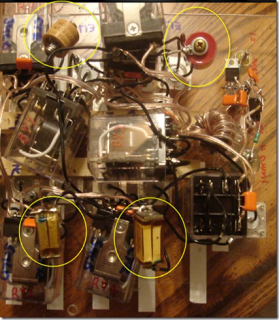
|