How complicated can a dipole be? Well, pretty complicated! Read on for details. Design ChangesThe dipole in the array serves 3 bands.
In addition, this element because of it's central location and large size has a lot of inadvertent resonant relationships with many other bands. In the original design, the dipole was detuned through relays in 3 ways: - Relays on the coax feed line at the feed-point could open leaving the dipole unconnected to the rest of the array
- A relay in the center of the dipole would allow for the normally open dipole to be shorted in the center doubling it's resonant frequency
- And relays about 5' down from the 12m trap ends could open leaving dipole halves which were naturally resonant about half way between the 20m and 17m bands.
Each of these options were under the uP shack controller's direction. And the system worked very well for the single-transmitter case. As with all the other antennas, under So2r, it's a bit more complicated. Adding Stubs into the Relay MixNormally I can treat the WARC bands, of which 12m is, separately because there are no So2r considerations there. However, in cooking up the hardware to do this, because the element serves as the DE for 12m, it's a factor. Fortunately, it looks like luck may have smiled on me... The model for this element requires this combination. And the plot points for the combined stub effect, based on the following chart, is listed as well. 160m - don't care 80m - open (for feed-point) - plot points 1,2 40m - short - plot point 3 20m - short - plot point 4 15m - open - plot points 5, 6 12m - open (for feed-point) - plot points 7, 8 10m - don't care - no plot but is shorted Note that the stub does not quite give a 100% short even in the 40/20m cases - but I think it will be good enough to serve it's detuning function and that's really what it's all about. Not making the element fully disappear, just transparent enough so that it does not get in the way of the other band/element functions of the various array parts. 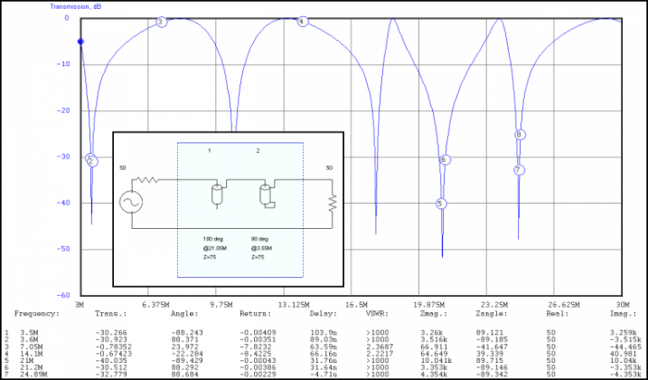
If it all works out as it looks, then this means that no switching would be needed for operation on all bands except for 30m and 17m . 17m actually looks like it would prefer a short but it looks essentially the same as an open, not surprising given the 50R-335j equivalent. For 30m, the stubs provide a 50R+330R equivalent and that looks mostly like an open to the 30m RF - which is not much of a factor in the pattern . While this is the PLAN, I think I will go ahead and equip this board with relays to provide bypass and open functions to the stubs - just in case REALITY is not quite as tidy as the PLAN! So the resulting schematic for the switching looks like this. A lot of the part count is dedicated to relay spike suppression and providing LED indication of the various relays - a very big help when the board is about 15 feet above ones head! 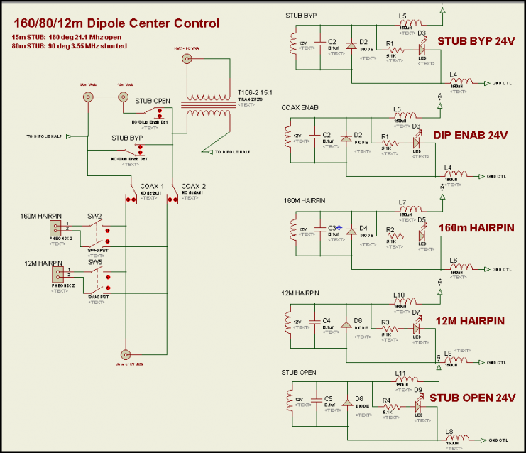
The normal facilities to open the center and disconnect the coax lines are included. In this implementation, there is not a true "short" option because the coax stubs are in series with the relay. In the normal configuration, the coax lines are enabled only when the antenna is fed. Notice there are facilities for 12m and 160m hairpins which would be switched on for the specific band. I use the 160m hairpin now as the loaded dipole at resonance has quite a low feed-point resistance. That's driven in part by the stucco coupling and in part by the loading. On 80m, by comparison, where the dipole is mostly in free space except for the ends, the feed-point resistance is very nice and no hairpin is needed for a nice clean match. ModelsModels for the 80m and 160m elements look like circles. Big cloud warming eggs. After a Q in the ARRL recent 160 contest with FM5CD, it got me to wondering - what do the low angle radiation patterns look like on this dipole for the 160m and 80m bands. Below we can see the 160m antenna, as modeled, is about 6 db below a full size antenna at the same height. That's about one s-unit. Now, looking at the 15 degree point, the gain change is about 11 dB further down. That's another two s-units. While 3 s-units is quite a change in signal strength, it's not as bad as I had expected. If the receiving station is running a similar low noise type of an antenna, and we have favorable propagation, then I can expect at least some of the DX stations to hear me. 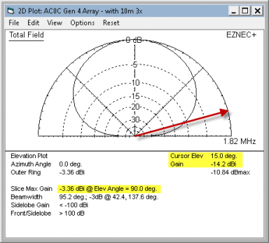
Looking at the similar case with 80m, the antenna has a gain of approximately the same as a full sized of the same height as it's not significantly loaded compared to operation on 160m. Gain change at 15 degrees is about 10 dB - similar to what we have on 160m. 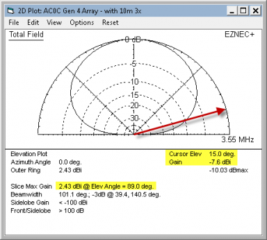
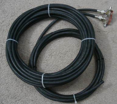
I'm not suggesting the antenna is a flame-thrower on 160m or 80m, however, the low angle radiation that most guys assume a low antenna is INCAPABLE OF - really is not as low as one would expect. Especially if the antenna's being fed with an amp on the front end. Testing the StubsThroughout this entire series of rebuilds, I have relied on stubs to do certain things that I have modeled. But I have not actually measured a stub when used in the series mode. Normally stubs are used to serve as a shunt at certain frequencies. And I'd thought of it - but just not got around to building a jig to do the test - until today. This is also the first time that I used two stubs in a series configuration. 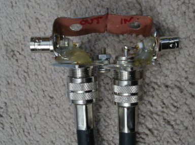 At left, the jig is shown with a pair of stubs connected. I have a set of PL259 shorted tips that were used to do a quick OSL cal on the jig. The VNA is connected via the BNC on either end. The construction is of the quick and dirty variety - with lots of hot glue serving duel roles of insulator and providing some mechanical integrity. At left, the jig is shown with a pair of stubs connected. I have a set of PL259 shorted tips that were used to do a quick OSL cal on the jig. The VNA is connected via the BNC on either end. The construction is of the quick and dirty variety - with lots of hot glue serving duel roles of insulator and providing some mechanical integrity.
I thought about the jig and it's applicability to the actual use - in that each of the center switching modules had a different layout. But in the end, I guessed that the jig would work well enough for giving a rough estimate of what the element should see. 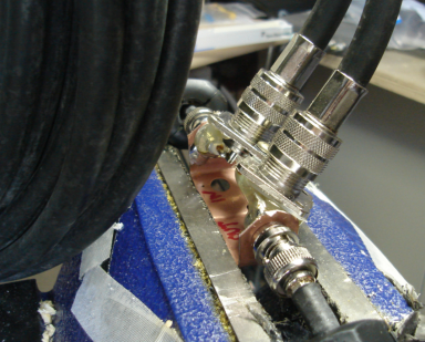
Here is the jig in action. Held in place by a vice. With the 15m and 80m stubs attached. Looking now at the stubs individually, first the 80m quarter-wave shorted stub. It's task is to provide shorts on 40/20m and opens on 80/12m. The stub was trimmed for maximum isolation on 12m as that's the most sensitive point for this stub. Results as measured in the jig for this stub are shown below. 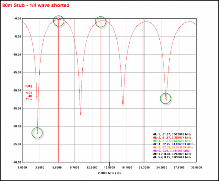
Because the 80m stub is a short on 15m, the added half-wave 15m open stubs assignment is to provide an open on that band. Below is the plot of that stub. Note the small dip just to the right of the 40m operation point is interesting but I did not dig into it's source as it's not significant. 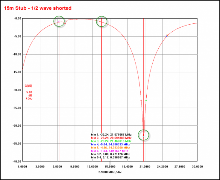
 And here a transmission plot of the two stubs in series, as measured using the test jig. The key function points are circled. The 40m and 20m are not quite loss free - but in this application, we are shorting these elements to detune them. So we really don't need a perfect conductor - just enough of a connection between the dipole halves to keep the element from absorbing power on 40/20 - as would be the case if the dipole were insulated in the center. 15m likewise needs the element to appear open for least coupling, and the 15m stub gives a very nice dip for that purpose. And here a transmission plot of the two stubs in series, as measured using the test jig. The key function points are circled. The 40m and 20m are not quite loss free - but in this application, we are shorting these elements to detune them. So we really don't need a perfect conductor - just enough of a connection between the dipole halves to keep the element from absorbing power on 40/20 - as would be the case if the dipole were insulated in the center. 15m likewise needs the element to appear open for least coupling, and the 15m stub gives a very nice dip for that purpose.
Likewise, at the key frequencies where the element is going to be fed with power, 80m and 12m, the tuning of the stubs pays of here with quite nice values of isolation. For 160m operation, the center stub set is going to likely throw off the SWR (best case) and dissipate too much power (worst case). For that reason, the stub-open relay can be tied to the 160m hairpin relay via the terminal block - isolating the stubs. Compared with the Elsie model, the stubs on 40/20m are about 0.5 dB more lossy. There is more interaction between the stubs on the peaks adjacent to the 15m trap. And the ultimate peak notch of the dips is a bit less. But overall, I feel there is quite a good match between the measured and the modeled use. And that is a HUGE relief given the amount of work that has been done so far - under the assumption that the stubs would work as modeled!!! 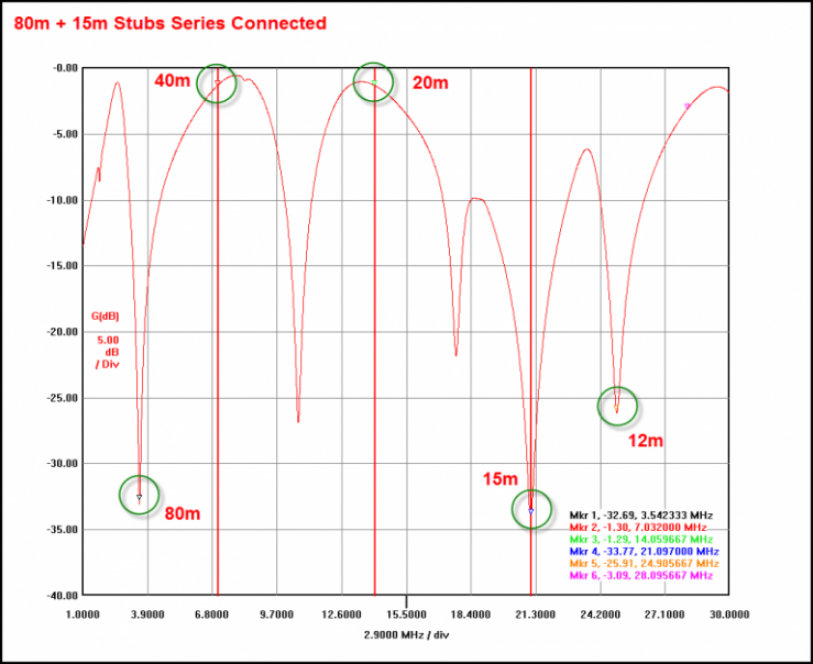
Build Details Having satisfied the question of "will the series stubs actually work" - it was time to build the control board. This is the most complicated of the center boards, simply due to the relay head-count. Parts placement was tricky while trying to keep some sense of symmetry on the board and keeping leads short. Not listed on the drawing are 6 LEDs which indicate the various relay activations. Hopefully saving me a rafter climb up to the attic apex when confirming relay activation. Each relay has series 150 uH inductors on each leg and is clamped with a diode and 0.1 uF cap to control the inductive kick. The RVM sensor shown provides the drive reference level for the 12m beam. 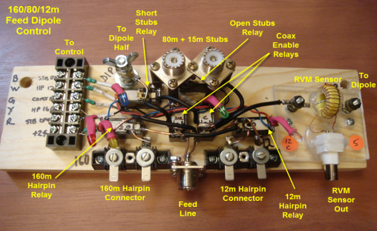
The only difficult part of the build was trying to keep leads short.
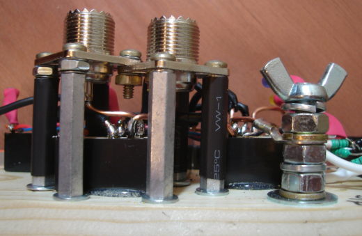
I did not want to inadvertently "lengthen" the stubs through wiring which would have the effect of lowering the frequency at which they were so carefully trimmed. The solution, suggested by the earlier jig construction, was to use stand offs as seen here at left. Below the control head for the 160/80/12 dipole shown mounted. 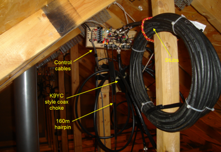
Results |