Going High-Q and High-Tech with the RX Loop at AC0C To address my terrible top band noise problems from the in-attic wrap-around 160m antenna, a big proponent of loops has been topbander Mike AB0X. Mike's racked up a huge DX count on 160m over the years working with his city-lot space and has built quite a number of loop variants. And he was right - the loop is a nice performer. However, the way I built it, with the direct transformer connection and implementing the multi-band capability with the nested loops had a couple of problems. Take a look at the prior version of the loop HERE. A loop's naturally high-Q capability is damped by the loading of the transformer. While the loop's bandwidth is pretty wide in this case, amplitude really suffers. And from the standpoint that the loop is wide-band by compairson to what it could be, that means the loop's pickup of the local BC station energy is higher. And secondly, while the 160m perfromance of the nested variety was good, the 80m and 40m inner loops was moderate to poor. I suspect this has to do with the nesting itself and interaction between the loops. Major Design Changes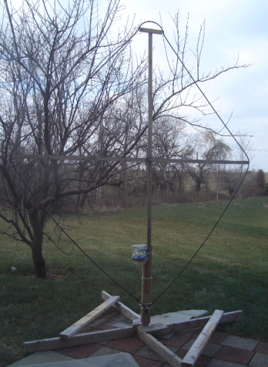
To address these problems, two changes were made. First, a high-z buffer taken from an old Demaw design was added at the base of the loop. This resulted in a very high Q and as such, quite a narrow bandwidth response. A series of relay-switched trimmer caps was added to allow for precision fixed tuning. And a second tuning method using a vactor diode was added to give continuious coverage. The actual loop performance of these two tuning methods is about the same (the loop Q is unchanged with the vactor diode vs. the air/mica caps) - but I worried that in So2r operation I would not be able to clean up the vactor line enough to eliminate jitter on the tuning line. The relay-swtiched method of course would be solid but limited in that it reflects fixed presets. Second, the loop was slightly resized with a natural resonant frequency of about 4 Mhz. 40m operation was eliminated totally. And the switched cap/vactor tuning method mentioned earlier is relied on to give 80m and 160m coverage. Gone are the 40m/80m dedicated inner loops in a "quad" outline format. Design DetailsThe shack mounted control head is modified from the prior version of the loop and uses the same AVR uP. Here the function is somewhat simplified in that the uP handles the user-interface and toggles the relays that do the actual work out at the loop tuning module. The loop buffer circuit has a pair of J310 feed directly into the gate from the loop. The input Z seen by the loop is the gate impeadance and as such, is negligably loaded by the buffer. Transformer build and bias currents were adjusted so suit the J310 from the original Demaw design. Notice the 7-pole LPF network buffering the +12v line. Current draw is around 40 mA for the pair. I did not have any FB at the time, so I used a couple of small type-61 ferrite cores on each drain. No instability has been observed. 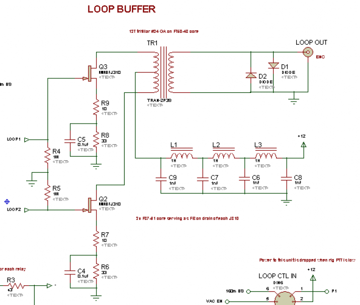
Tuning of the loop is accomplished by a series of relay-switched variable caps. The relays are configured in a binary fashion so that the values are cumulative for a band. 160m and 80m are padded seperately. The 80m PAD (lower left) tunes the loop for the upper 80m RTTY band at about 3585 KHz. Because the loop's natural frequency is quite close to the top end of 75m, very little additional cap is needed to resonate the loop. The loop is tuned down further into the CW band through a combination of PAD-1, or PAD-2 individually, or PAD-1 and PAD-2 together. The combo gives a total of 4 tuning points for 80m. 160m operation is similar. Initial tuning to around 1860 KHz is set by the 160M PAD cap. And as with the 80m example above, combinations of caps 160-P1 and 160-P2 provide 3 more tuning points. Here the initial trimming provided center points of 1860, 1840, 1825 and 1805 KHz. The input to the pad circuitry (and to the delicate high-z buffer stage) is protected by the small relay at the loop input. When power to the loop tune module, the protection relay is engaged connecting the loop to the tune/buffer inputs. When the shack-side rig's PTT line is set, a set of buffers and a relay in the control box cuts power to the loop tune module causing the relay to release - and shorting the J310 inputs to the buffer ground. This action also detunes the loop reducing the voltage across the loop terminals as well. The comb of actions proved to be very effective at preserving the J310 - of which I had fried a few in earlier trials with power on the nearby transmitting antenna. And the relay with it's 1 mS response time is faster than the transmit side delays (of around 15+ mS) ensuring no hot-switching is taking place. 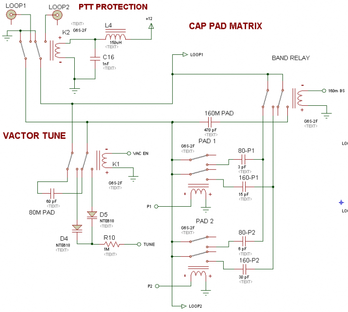
The PTT line buffer uses a hex schmitt trigger buffer/driver to key a very fast reed-relay. The reed controls the power feed to the loop tune module. A side-benefit of this feature is that possible uP code writing mistakes - which may cause time delay in execution or some other problem - will not put the loop at risk in the face of RF. The loop protection functions independently of the uP. 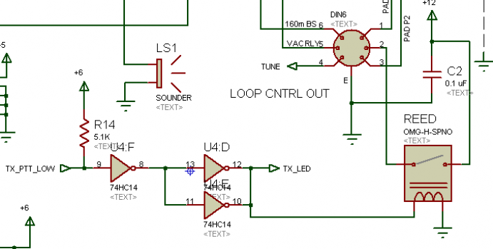
In the vactor tune mode, voltage for the vactor tune is supplied through a +12v 3-terminal regulator which feeds a TL431 precision reference (schematic below). This sets the max voltage for the vactor tuning. A 7-pole LPF follows that and the clean reference voltage feeds a pair of resistors. The tune voltage is set with a 10-turn pot. And the min voltage range is set by the trimmer. Adjusting the trimmers properly gives smoothly tuneable loop coverage from about 3.95 Mhz down to 1.795 Mhz. Due to the loops high Q, the peak is eas to detect by ear or by a rise in the bandscope. 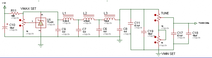
Build Details - Loop Tuning ModuleJust about every part of this design was unproven (by my personal experience anyway) and so the construction of the loop tuning module and the shack-mounted control box was done in a FUGLY (fantastically ugly) breadboard style. The good news is that the design actually seems to work great, despite the amazingly lousy implementation. Shown below is the loop tuning module. The entire function of this box is to provide these features: - Tune the loop to resonance on preset 160 and 80m frequencies via a relay switched arrangement.
- Alternativly, allow for varctor diode tuning across the entire 160/80m band
- Buffer the loop with a high-z FET stage to preserve the loop's highest possible Q
- Detune the loop and disconnect the high-z buffer when PTT is asserted in the shack to protect the loop from RF
Shown below s a top view of the loop tuning module. 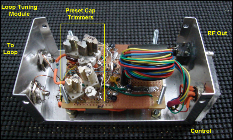
Here we can see the bottom side of the board. The loop buffer to the bottom right was the first thing constructed. If I were to do it all again, I would provide a bit more board space to work with... 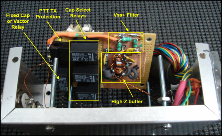
The control and RF lines are seperate which allows for maximum seperation of RF and control noise. The case is connected only to the loop shield. The board ground floats with respect to the case to avoid ground loop pickup - all grounds are connected at the shack control side. The BNC connector is insulated by design. Needing all lines on the BNC including the shell, I used a bit of PS scrap to provide an insulating function for the control line connector. All control lines are routed through a multi-turn type 31 ferrite before terminating on the board connector. 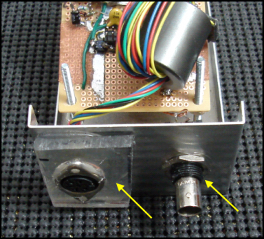
The lines that connect to the loop tune module are likewise built for common mode rejection. 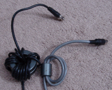
Build Details - Shack Control Head The shack side loop control head is a modified from the prior loop control to accomidate the additional features. Orange button - Loop enable/disable function. Allows for easy comparison with the dipole. Blue button - Selects Vactor or Relay-Preset tuning method. If Vactor is enabled, the left orange LED is lit. Vactor tune knob - Adjusts the loop's resonant frequency Blue LED - Shows when the PTT line is set by the rig Gray buttons + 4 yellow LED - steps through the 4 loop preset tuning frequencies. The uP remembers the last setting for both the 160m and 80m bands so that readjustment is not required. 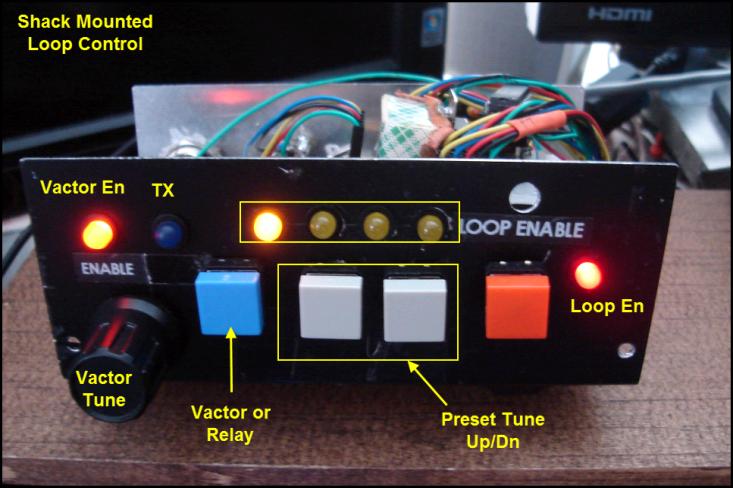
Internally, a bit of wire changing was needed on the uP I/O to match up with the new requirements to drive the relays. More importantly, the vactor diode circuitry was built around the 10-turn pot as a mechanical foundation. All the filtering is done here - and bypassed again right at the loop control jack for good measure. The PTT bypass buffer was added in after-the-fact and was a rush modification to get me on the air to participate in the ARRL 160m CW contest. I will have to pull this apart and clean up the wiring and mounting a bit later. 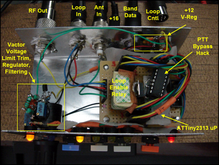
Results Below a plot using the fixed-cap tuning method on 80m: CF 3585 khz - 19 Khz @ -3db, 33 khz @ -6 Khz. Note: the response is actually smooth - the white shading is a artifact of the test method. 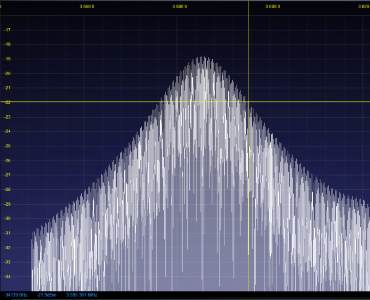
Below a plot of the 160m fixed cap trimmed to about 1830 KHz. -3 db bandwidth is about 24 KHz. -6db ~ 40 KHz. The spikes on the plot are some strong CW signals on the band. 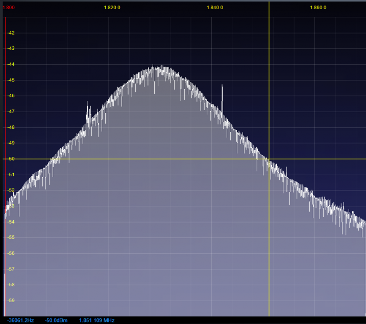
And for comparison, below a plot of the varicap mode, set to the same frequency as the fixed cap above. The bandwidth is almost exactly the same suggesting the limiting factor for Q is not related to the tuning capacitance method. 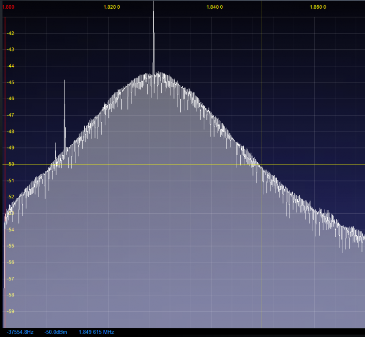
One interesting benefit to the high Q buffered loop. The signal strength of this antenna is roughly the same as the dipole. However, the diople "sounds" louder because the noise content of the dipole is higher. |