Noise is the constant companion of the stealth antenna warrior. And as the 160m season heats up this winter, the noise level of the house with the attic 160m dipole was a serious limitation to doing any real work on that band. I had not considered a dedicated receiving antenna but a friend Mike AB0X has had excellent results with loops and that was always in the back of my mind... With the Stew Perry 160m contest coming up, I convinced myself that a receiving loop was the next step in antenna work needed. Where to put the loop was the next big issue to resolve. Initially I had considered putting it in the attic - but that space is already past it's limit of antenna complications with the current antennas. So the logical step - and one that would offer the best chance at noise reduction, would be to put this on the patio. That of course would invite neighbor comments or a possible visit by the HOA for "consultation." Caution goes to the wind! [And so far, so quiet=good!!!!] 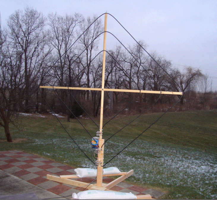
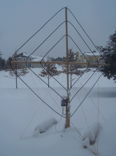
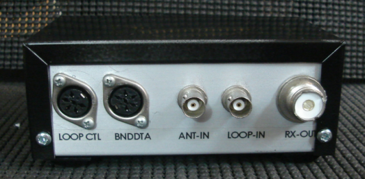
The loop is the unshielded type constructed from RG-11. The benefit of the shielded type loop construction seems to be in loop balance and that is said to improve null depth. However, in my case -with plans to have a stationary orientation, moderate loop nulls are beneficial. The orientation of the loop is ENE-WSW which aligns nicely with the coast population centers. And this also allows the null to be focused at the house which I expect is the primary source of QRN. An excellent summary of various coupling methods - and a short discussion of the shielded vs. unshielded loops may be found on W8JI's web site HERE. There are separate loops for 160m, 80m and 40m. The feed lines are run separately from each loop to a switch box mounted on the antenna. A single coax and control wire feeds into the shack. The outer 160m loop is 8 feet on each wooden cross element - making the circumference about 22 feet. The 80m antenna is spaced in about 1 foot from the 160m - and the 40m is spaced in about 1 foot more beyond the 80m. At the shack end, a control box is fed with band-decode information from the Ameritron RCS-12c - and automatically selects the antenna based on the rig's current band selection. The control box also switches between the normal antenna and the loop. As well as providing isolation features to ensure the loop is disconnected during transmit. The interface to the feed line follows Rick N6RK's general design which uses a resonating cap and a paralleled step-up transformer built from type 61 material. For more information on Rick's excellent work as published in the NCJ, click HERE. 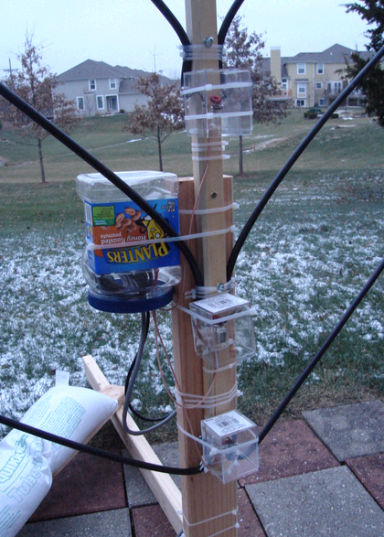
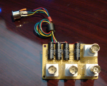
Given the future of the loop was completely unknown, the loop's physical construction took the functional focus only. The inverted plastic containers served to keep the rain out and has the advantage of not trapping moisture. However, with some kids in the neighborhood, I worry that a "hea, look at the cool little things inside the boxes” urge will end up drawing unneeded trouble. So after finalizing the tweaks to the design - and assuming I don't get thrown in HOA jail, I will spray these boxes with a black paint to hide the contents. A black box is a lot less interesting that the clear ones… Remote Antenna Switch BoxHidden within the larger of the inverted containers is the antenna switch box. Inside the switch box are a set of 4 reed relays. The 3 relays on the left select one of the 3 antennas. And the relay on the right shorts the loop input on transmit – hopefully keeping any RF the loop or it's feed/control lines pick up – out of the shack…. There’s a set of IMD generating diodes back to back across the loop feed to the shack which you can see below. This is almost universally a bad idea although it's very commonly done. I think a lot of ops don't realize how easily BC band energy can push the diodes into conduction. However, in this case, I think I can get away with it here. The loops are amazingly high in Q which means the loop will attenuate BC signals to begin with - and the loop's voltage levels are quite low vs. the full sized station antenna (down about 12-15db on 160m). The ferrites and the blue caps are there to help keep the control and feed lines clean. 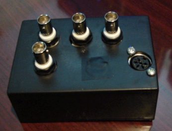
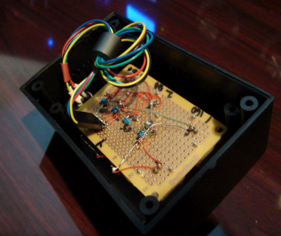
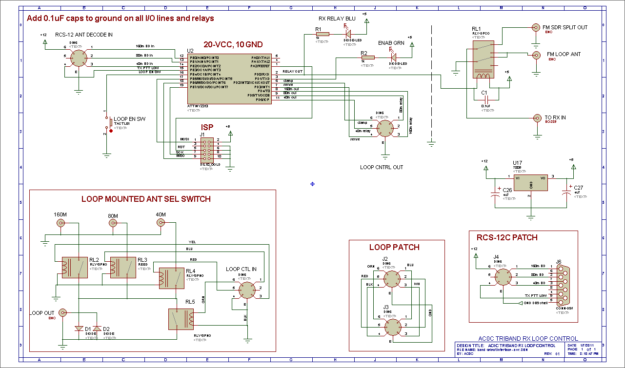
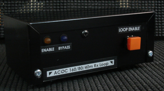
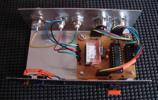
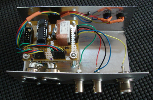
Shack Mounted Loop Control Head The control head is simple in component count - containing a relay for the antenna source selection - and an Atmel AVR micro controller to provide all the switching I/O control sequencing. The AVR was selected because it turned out to be far simpler to put the functional code in software than to implement the features in discrete hardware. Specifically, the functions of the control head are: - Select the loop antenna based on the Ameritron's BCD aux output
- Switch between the normal antenna and the loop
- Disable the loop and short the RX input while in transmit to avoid any RF present in the event the loop were to pickup significant amounts of the TX energy
- Bypass the loop when the rig is set to bands other than 160/80/40m
The only control for the operator is a LOOP ENABLE switch. All other aspects are automatically addressed by the control head's micro controller. One feature not yet implemented - but would be easy to do - is to provide a "memory" of which bands the loop is selected on. So that when switching between bands, the control head would remember which of the 3 loop bands the loop was enabled on - and which bands it was in a disabled case. The schematic below shows the simplicity of the system, when the AVR handles all the switching details. Click on the schematic for a full-sized version. There are many other ways to implement a multi-band loop - N6RK uses the vactor diode tuning method which is a great solution if you want to have full coverage over a given band. A very interesting tie which the AVR would support is to read the rigs frequency either by RF sampling or directly from the rig's CAT feed and then, via the AVR's DAC, provide the proper voltages to the vactor diode - allowing the loop to track the rig's frequency. 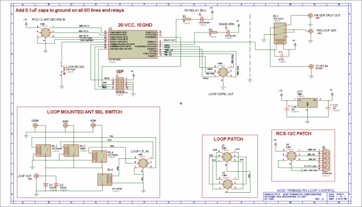
Performance and Observations (all elements UNSHIELDED STYLE) The loop's performance in the Stew Perry 160m contest was just fantastic. I had the loop enabled the entire operating time and perhaps 2/3 of the QSO would not have been possible without the loop. The loop on 160m is a clear winner! Initial op time suggests that the performance advantage of the loop drops with each of the higher bands. Performance seems about tied with the 80m full-size dipole - if the local noise sources are contained. But on 40m, I believe the 2-element reversible beam is the better performer. On the other hand, it may be possible that the loop needs a bit of amplification to perform well on these higher bands where the low signal level combines with increasing coax loss resulting in signal levels on 40m which all combine to give the rig too little to work with. There may be a performance compromise on the higher bands due to the loops construction. This is one project where I specifically did not do any modeling work simply because it's about as easy to build the triband version as a single band version. MMANA-GAL will hold the answers here.... UPDATE: Conversion of the 160m element to the Shielded StylePrior to the CQ160 contest, I changed the loop design to a shielded type of constructions. The modification is simple to do - it involves cutting a not out of the center/top of the loop leaving only the center conductor. And then adjusting the capacitive value needed to resonant the antenna again on 160m. The entire process required about an hour. Fortunately, the weather that day was cooperating! The goal of the move to the shielded style loop was to determine if there was a more pronounced null effect observed. The key attraction of the shielded loop is that, because of a more ideal balance, the null is deeper than in the unshielded case. Performance and Observations (160m element now SHIELDED-STYLE)The loop was an outstanding performer in the CQ160 contest. The loop was the better performer (from a signal-to-noise) standpoint for all the US/VE/XE contacts. The loop (shielded or unshielded) has tended to be the better performer regardless of how quiet the band is on 160... There was a bit of DX on the bands that I could hear - and I did find better DX performance with the full size antenna compared to the loop for those few that I worked including a few M0 region and several Caribbean stations. The low angle performance of the loop at ground level is not good and I think that's the reason for the improvement in DX signals of the full size dipole vs. the loop. The side rejection nulls do seem to be more pronounced with the unshielded version - because I did seem to have a more difficult time working signals that were in the estimated location of the null. I also ran the loop (using the 80m capability) for some part of the CQ WPX RTTY contest. For the domestic region, it was generally speaking as good as the 80m full size dipole. If the band is noisy then the loop is a better performer. If the band is quiet, then the loop does not show much advantage. Although I generally like to use the loop because it has a way of making the time spent on these bands with noise much less fatiguing. Overall, I would recommend others to build the shielded style if the null to a local noise source is the goal. In my case, the loop must remain about 10' or so from my house location (more spacing would be better). And because of that, I wanted to be able to set the loop so that the noise from the house would be in the null. The shielded variety is supposed to provide better null although I was unable to try a true A/B comparison. However, if you are able to set the loop further away (so the objective is to minimize the general atmospheric QRN instead of a point-source local noise issue), then I would probably go with the unshielded variety because it tended to have a bit less of a directional null - yet it provides about the same level of QRN reduction from the background atmosperics. Looking ForwardSome more experimentation remains... 1. Why the loop performs so poorly on 40m vs. my wire yagi? Is it the difference in TOA? Or is there something I have overlooked on the 40m design (would a stand-alone loop perform better than the current 3-in-one-plane design?) 2. The 80m element could be removed if the 160m were to be a bit shorter (it's naturally resonant at 3.460 MHz) - and then both 80m and 160m could be covered with switched in capacitors driven by relays right at the loops feed. If there is a negative influence on the 80m by the outer 160m (unproven), then this is one way to address that problem. 3. And while the signal level is adequate on 160/80, a antenna mounted LNA would be helpful because that would push the rig's signal up to the point where the AGC would engage more. 4. From a user standpoint, I find the small T/R DIP relay used in the control head to be a bit noisy (from a sound standpoint). For contest work, I like to try to minimize the noise in the shack and some sound damping needs to be added to the control head. |