Quiet, low TOA, mono-band - a perfect stealth omnidirectional solution This antenna summary is from an email I had sent to the guys who helped me out with the technical details. This was my first experience with antenna modeling and with the MFJ 259. There are two major parts to the antenna. A set of 3 full-wave loops that share a common feed-point. And then a dipole that runs around the permute of the attic and forms nearly a complete loop. A MFJ 929 auto-tuner provides matching as needed, as well as switching between the two antennas. A single coax runs to the shack from the tuner. Some modifications to the tuner allowed for shack-based control of the tuner. Top-view Array Layout 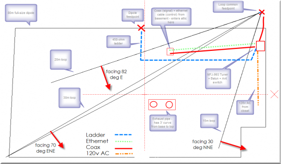
Perspective 3-D View 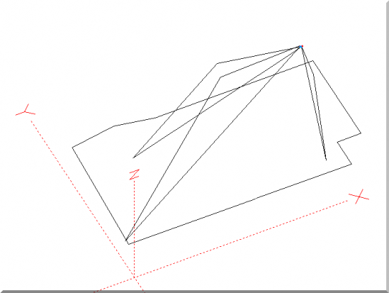
Letter to My Elmers16 Feb, 2009 Gentlemen, Thank you each for your individual contributions to this project. I really do appreciate each of you serving Elmer duty and expressing an amazing amount of patience... I’ve documented the final configuration below in some detail for my own records, and for those interested in how it worked out. Performance of the loops vs. the perimeter dipole shows an average S4 reduction in noise level. And there’s quite a difference in what signals show up on the dipole vs the delta loops. Thanks a million to Rob for pointing me in the direction of the corner-fed delta loop... Unfortunately, I’ve not yet had the chance to take advantage of the lower TOA of the loops because it seems these past few days the bands have just been lousy... Got quite a bit of central America and Western DX showing up tonight though – and these signals are far more clear on the 20m loop than the dipole.The loops were initially laid out differently and looked great in the simulation. Tests with Rob and Bill showed the performance of the 20m was not correct in reality. And after quite a bit of digging, there ended up being 2 problems. The attic is pretty much open space except for some surface wiring for lighting and smoke detectors. And there is a furnace exhaust pipe that runs up through the center. In retrospect, I don’t think these items created the big problems I had on the 20m loop when first put up. The initial simulation layout had a few problems. - The model was constructed incorrectly, the interactions due to proximity of the loops was not showing up. I think that’s what caused the 20m loop to work so poorly. The specific problem was the construction of the common feed-point for the 3 loops in the first simulation.
- After that was fixed, the interactions showed up leading to the configuration and (rotated) spacing as it’s shown below. From the model, the layout has minimal interaction although I did not attempt to map out the exhaust stove pipe or attic flooring lighting wiring.
Based on John’s comments, I’m very sure that the models - and the actual performance of the array - are two completely and totally different things. I appreciate John pulling me back to earth on the expectations of the model. As the frequency goes up, the loop positions relative to other become more sensitive. And the geometry of each loop strongly alters the SWR. The ideal angle for the apex seems to be around 126 degrees for the minimal TOA and reasonable SWR match. I was able to get near this in the attic although the far ends (away from the feed point) are tilted up slightly on that end to provide more clearance between the attic floor and the antenna base. No surprises in the construction other than the actual tuned length seems to be somewhat shorter than calculated. Perhaps by 5% on the loops (and about 10% on the dipole). I did not measure the amount trimmed – too hot up there. If anyone has an explanation of that I would really like to understand the gap between modeled vs. real. The models suggest a the loops favor the SSW direction in some cases (especially on 15m), and that by moving the feed-point to the opposite corner that could be flipped around to the NNE. However, I decided that given the amount of additional feed, power and control lines that would need to be run to make this happen, and the assumption that the models vs. reality were probably already quite different, I left the feed point in the upper right location as shown. The loops are more or less omni-directional and 1-2 db difference is probably nothing I would notice in practice. Not shown are all the ferrites spread around up there. I used about 30 snap-on ferrites – about 12 of the largest ones are used on the feed line from the loop to the tuner, and from the tuner output coax... This serves as a current choke to help keep the coax from radiating. And the rest are put on along the coax, tuner control ether net line and power lines at various points. All of these cables are in close proximity to the radiating elements and hopefully the distributed ferrites help to keep the induced currents checked. I’m not sure what the susceptibility of the Ethernet cable with its 4-set of twisted pair cables would be. But I coiled up about 12 winds x 4” dia just for good measure... I don’t have a good way to measure it, but compared to the prior open-wire fed 20m double-extended-zepp, it seems I have less RFI pickup in the various house electronics using either of these antennas, on any band. The real test will be to see if the smoke alarms pickup power off the dipole on 160m. Need to wait till the wife is out of the house to do that test or risk near certain admonishment. Antennas were trimmed for these frequencies using a MFJ-259B (what a huge time saver there...): Dipole - 3.9 MHz (tuned for min SWR at the dipole feed point) 30m loop - 10.10 MHz 20m loop - 14.05 MHz 15m loop - 21.1 MHz I realize the tuner makes the trimming inconsequential from a match standpoint, but Rob suggested making the antenna resonant at the target frequency as a way to hopefully max the antenna efficiency. And it was a good excuse to play with my shiny new -259B. The MFJ provides automatic fine-tuning and the antenna switching capability (controlled from the shack). It’s also got a balun built in to take care of the open wire feed as well. A very cool box for the price... The dipole loads up on all bands and is a good performer on 40/80. It will load up on 160, but the efficiency suffers on that band due to the short length in the simulation (-3db down) but I imagine the real performance killer is the low Zr/Zi combination - I’m sure creates a lot of loss in the tuner to match this value to the coax. The simulation predicts the existing loop 40m performance to be down about 2 db from a full-size loop - but I’ve not yet found a case where the loop was providing better reception performance than the dipole from a signal strength standpoint. Hard to tell because we’ve had some evening showers in the area and 40/80/160 have just been too noisy to do a real comparison. I’m very happy with the result. And have learned a lot about doing the simulations – and their difference between reality and ideal. And lastly, just how hot an attic can be in the summer time... There’s a ham tradition that says “the colder the weather, the better the quality of antenna work you will do.” I can tell you that in the opposite case, heat, it’s not true at all! Putting up antennas in the cold is far preferred to the heat, at least from my perspective! 73/jeff/ac0c Build DetailsThe delta loop is easy to put up in the attic environment but there are a couple of things that will make the job easier: 1. Use flex-weave or similar high-flexible stranded wire. Flex-weave is more expensive than THHN stranded but it will not stretch much. If you use THHN, plan to let the antenna set under tension for a couple of days for the wire to stretch out. 2. The delta loop will need to be corner fed . Here's a picture of the way I did it. Keep the corners fixed and trim the length at the center of the base of the antenna. Note the multiple clamp on type 31 ferrites serving as the coax transmission line choke. 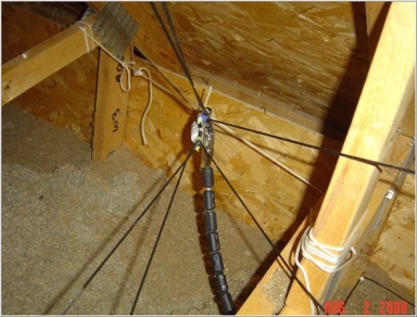
3. For the other two corners, use a plastic clothesline pulley like this model from Home Depot. Bungee cables run from the pulleys to the support point. 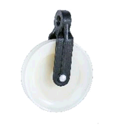
4. The antenna feed-point will be in the 50-200 ohms range depending on the surroundings. The antenna can be fed with open wire feed or with coax as long as a good coax transmission choke is used. Jim K9YC has an excellent series on construction of transmission chokes that is highly recommended. At the center of his work is the type 31 material which is really ideal for HF chokes. A high performance choke is important in the attic application because small amounts of residual RF on the feed-line will be closer to the house electronics than with an exterior antenna. To see Jim's work, click HERE. Loops on 15m 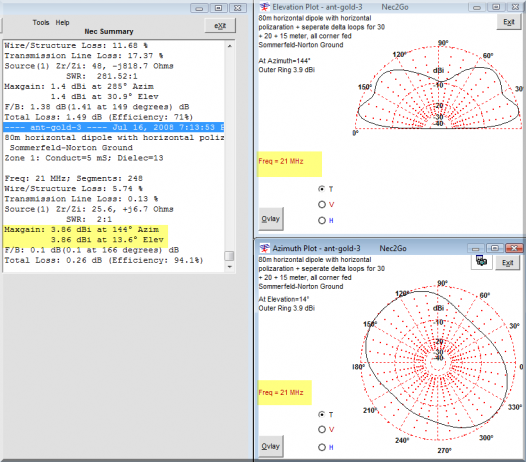
Loops on 20m 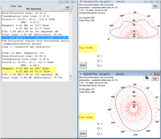
Loops on 30m 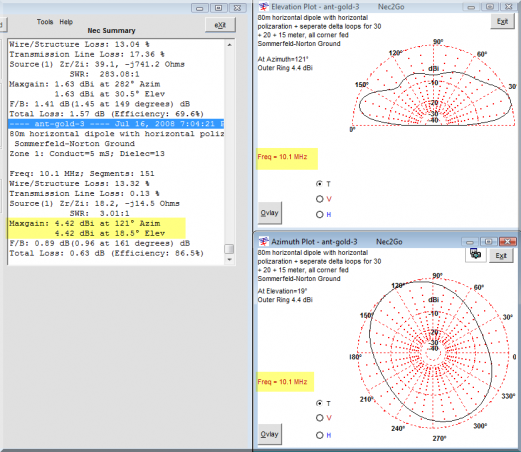
Loops on 40m (requires tuner) 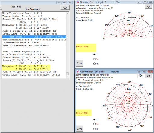
Perimeter Dipole on 20m 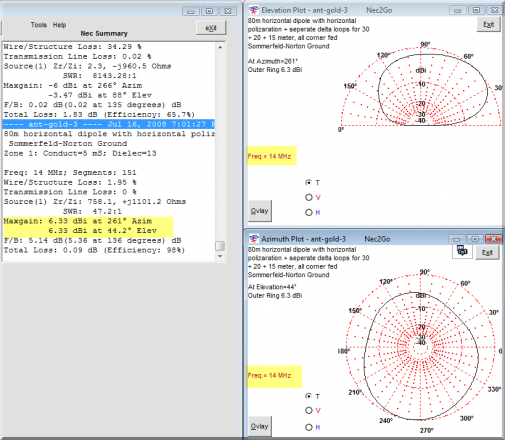
Perimeter Dipole on 40m 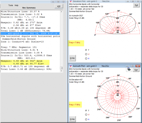
Perimeter Dipole on 80m 
Perimeter Dipole on 160m. Check out that Zo! 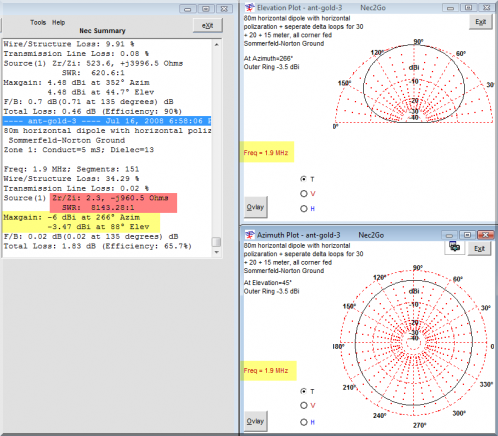
|