OWA Designs Offer Solid Performance with Wide-band Characteristics 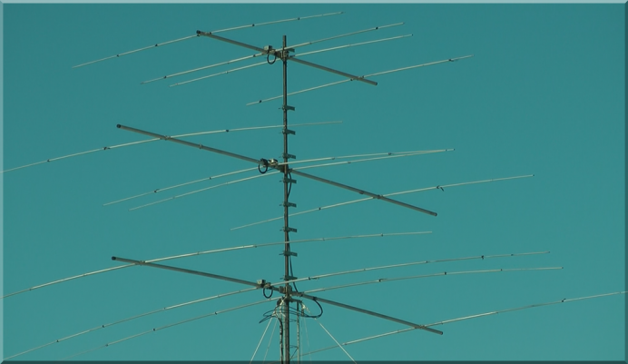
Beam design was a tough challenge. Mono-band stacks were the ideal solution for So2r. However, a single tower stack has interactions with the higher bands which compromise gain and F/B a bit. Further, the choice of beams was limited due to the tower - a 25G with temporary guys and base. Finally, while I prefer CW and RTTY operation, some of the guests want to conduct phone contests here and it would be nice if the antennas would not present a lot of SWR challenges. An OWA mono-band stack seemed a good overall design choice. OWA mono-band antennas are the choice of many contest stations because their flat SWR response makes amp tuning less critical as stations roam around on a band. And while not an initial consideration here, the OWA design simplifies beam stacking because the load is fairly constant over the band, reliable power splitting with stack matching hardware is easy. Credit for the OWA discovery generally falls to NW3Z Nathan and WA3FET Jim. The OWA design seems to have been first embraced by K3LR. Read more about that HERE. Fortunately with a freely available optimization tool (MMANA-GAL), you can easily realize your own custom implementation of the OWA without much modeling savvy. And while it won't be quite as ideally optimized as those at K3LR, they will for the most part offer the key advantages just like the big guns enjoy. ConstructionThe beams were built out of old Hy-Gain Long John beams. These were found used and the beam has a reputation for mechanical durability. The full length of only the 20m beam was used. While the other two beams could have been built with an extra element, the added gain and improved F/B were determined to not outweigh the added wind load. And at this QTH wind load and ice are serious problems. Design and Model ResultsThe OWA design was worked up using MMANA-GAL using solid, single diameter tubing for the first pass. After optimization was completed, the dimensions were used to roughly lay out the beam hardware. Measurements of the beams actual dimensions were then loaded into the MMANA-GAL taper schedule, and a final optimization series ran. This became the final dimension set and the beam's hardware was adjusted to match the model's dimensions. 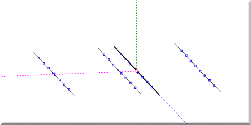
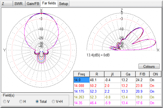
This is a typical OWA SWR curve. The second dip near 14.3 MHz is the effect of the close-spaced first director. 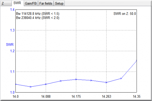
F/B is at it's peak on the CW end of the band. But the pattern is pretty stable over the entire band. Even though the beam is 4 physical elements, the close spaced director serves the SWR control function and provides little gain. So overall performance is similar to a 3-element beam. 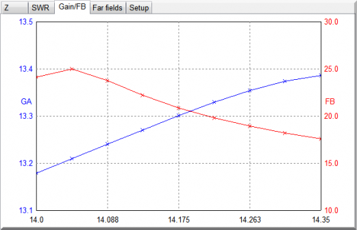
The 10-15-20 "Christmas Tree" Interaction CompromiseThe length of the mast and rotor positioning within the tower resulted in a vertical separation of only about 6 feet between each of the 3 antennas. Unfortunately, this tight spacing comes at a price. We can see here in this series of EZNEC plots what the antenna alone, and in the 10-15-20 stack (as built) looks like... Here is the basic EZNEC model, ported from the MMANA-GAL dimensions: 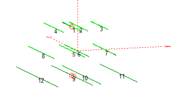
Comparing the 20m beam (alone) - to the 20m beam in the 10-15-20 stack, we can see little effect. About 0.85 dB of gain loss per EZNEC. TOA remains the same. 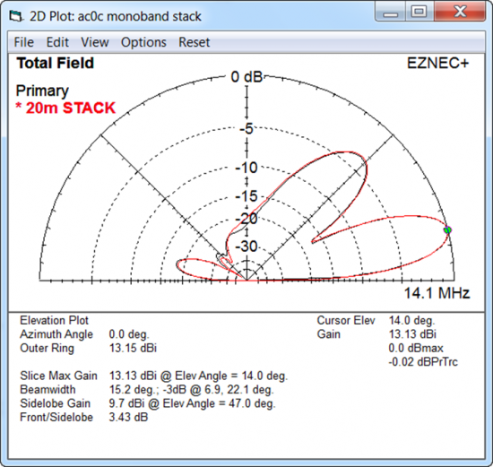
The penalty is more severe in the 15m case. Notice the pronounced increase in response to the high angle signals which will be heard as "more band noise." The high angle bump must come from somewhere, and unfortunately it comes out of the forward gain costing about 1 dB. The TOA is unaffected. 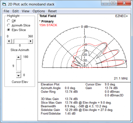
And lastly, we see a similar effect on 10m as with the 15m beam. More high angle response, at the expense of low angle forward gain. About 1 dB loss on the low angle peak, and an unfortunate one-degree increase in the lowest angle peak. 
While these response patterns look pretty bad in the EZNEC plot, they are not at all a practical limiting factor to the extent that you feel "the beams don't work." The beams have plenty of F/B when rotated, and the F/S remains sharp. This is the problem with EZNEC; it lets you see what you may be missing, even if what you are missing is nearly impossible to "hear." Of course, there IS a solution for what ailes us here. Unfortunately it requires additional beams and the formation of a single-band stack of a different sort! A delightful project - but one for another day. A Short Primer on StackingThe way to work around the interaction problem is to stack beams. A stack is the idea of using two (or more) of the same antennas spaced vertically at a proper distance so that their patterns reenforce. The benefits of a stack can include increased gain, elimination of the nulls in the pattern, and versitality - for example, one beam in a stack can point to JA while the other points to EU, allowing you to work both locations at the same time with a pretty good signal in both directions. The downside of stacks are that you more than double the amount of tower hardware. First there is the 2nd beam. And in additon to that, you have a feedline and a switching arrangement which feeds the two beams in a certain maner. The feedline lengths are important. You also need to run control wires out to the switching box so you can control the system. My Short Stacks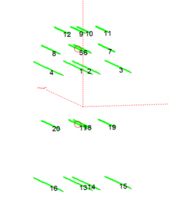 In the ideal case, you determine the stack height of each beam with modeling software, and then put them on the tower at these heights, or as close as can be arranged given hardware constraints (guy wires, etc). However, in my case, there was no possibility of moving the existing trio of antennas. In the ideal case, you determine the stack height of each beam with modeling software, and then put them on the tower at these heights, or as close as can be arranged given hardware constraints (guy wires, etc). However, in my case, there was no possibility of moving the existing trio of antennas.
So the first step in considering a stack for my QTH was to look at the pattern improvement of using a 2nd added antenna lower down on the tower, given the existing antenna height as a "fixed" constraint. The results were immediately encouraging. Starting with an EZNEC model, I duplicated the existing antenna dimensions and put the new antenna further down the tower. In the diagram, elements 17-20 (15m) and 13-16 (20m) were added with starting heights of 50' (15m) and 30' (20m). After some fiddling with heights, I obtained these elevation patterns (below), to which I have overlaid the existing beam (as it sets now in the trio on top) and in the stacked configuration (the two beams operating as a pair). 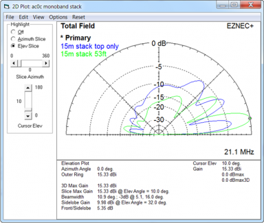
The 15m top beam really suffers due to the interactions with the 10m above and 20m below at the top of the tower. In the plot (left), we can give the award for "most improved pattern" to the 15m beam here - contrast the top beam (blue) with the stacked version (green). We get more forward gain - especially on the bottom lobe where we would most favor it for DX, less response to the high angle directions (meaning it will be quieter) by going to a stack. 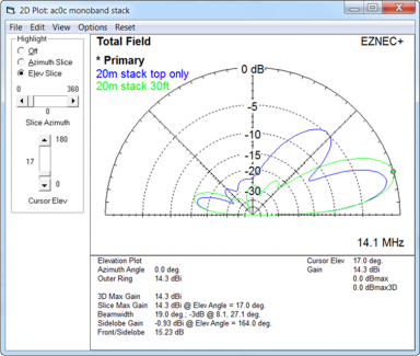
For the 20m beam, the top-only pattern is not bad, but with the stack, we consolidate all the power into a single higher-gain lobe that is also fatter (covering more vertical angles). Based on the graphs, I was confident that if a stack were put up, the performance would be an improvement to what is in the air now. Building a Better RF MousetrapFor these beams, a new tool was drawn into service, AC6LA's AutoEZ. AutoEZ is a front-end tool for EZNEC that provides a ton of power-user class tools by combining Excel with EZNEC, and of these tools, the most important is the ability to perform optimization similar to what I had done with MMANA-GAL, but with the precision that EZNEC brings. Because I used antenna parts from whatever I could scrounge up, the process for building the beams worked like this: 1. The approximate lengths of the 4 elemements of the OWA were known from the prior design. So the basic antenna was cooked up from the yagi bone-yard parts. 2. The physical yagi taper were measured and that was fed into AutoEZ as a "taper schedule." 3. Then we let AutoEZ work it's optimization magic by adjusting the 4 element spacing as well as the tip lengths. 4. Once an optimized design looked like a winner, I would adjust the physical beam to those dimensions. 5. Measure the R/X curves of the beam at height, and compare with the model. Adjust the beam dimensions to make the measured values match more closely the model. Repeat as necessary. The build is pretty simple up until you hit step 5. And if I had used insulated elements, I think that the measured beam and the model would agree quite nicely meaning step 5 would be just a little tweaking event. But because my bones were of a grounded element type (mostly Hygain LJ parts) - and given the OWA is pretty sensitive to things like the small differences that a grounded clamp vs. insulated element provides - that step 5 was pretty involved. It took about 2 weeks to get the two beams dialed in to what you may consider "close enough." Sidebar: If you want an easy project, use insulated elements. That's what the big boys have done historically. Lately there is some interest in using grounded element designs as that may be quieter (although the verdict on that seems to be the subject of considerable debate), but to do that you introduce a lot of variables. AC6LA has done quite a bit of work on the use of adjustments to dimensions to comprehend the clamp's effects (drawing on some work of the "antenna greats") but in my case, I just could not get a close fit. So while the work continues, I think that in the future there will be some tools available - or at least a generally applicable method to roughly adjust for the grounded elements - which will make this process easier. Physical Construction 15m Beam R/X and F/B Plots 20m Beam R/X and F/B Plots Stack Control & Phasing SystemThe phasing 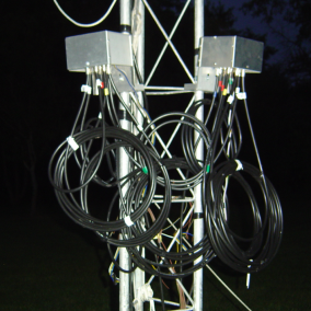
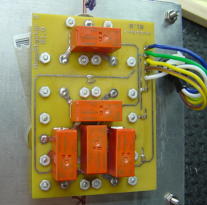
About The Coax Lengths... The Finished ProductThe lower beams are visible in this shot. The top trio is beaming JA, with the bottom beams fixed on EU. The split direction use is one of the unexpected benefits of having the stack. 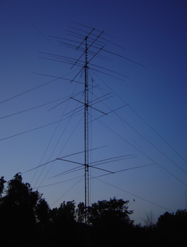
A shot looking up the tower from ground level. 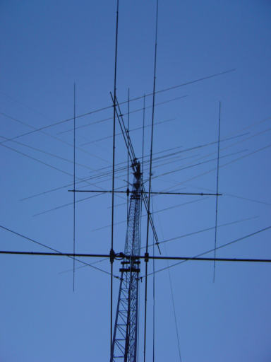
Special ThanksTo W8WWV for his work with the development of the Monostacker board, for taking time to look at my work and help point me in the right direction. To Dan AC6LA for his work on the AutoEZ, which makes working with EZNEC a lot more productive and "EZ" - as well as his advice on my models, especially the shortcomings thereof. To K0LW for the bracket materials holding the beams to the tower - as well as for providing me with a lot of materials used in the station's antennas. To US Towers for the use of their excellent tilt power trailer/tower - which saved me a lot of time in the sun and for which I'm very grateful. And to K0VXU for coax used in the phasing line construction. |