Coverage for the 3 WARC bands and 6m is provided this way: 30m - Vertical dipole suspended off the main tower 17m - Homebrew 3-element yagi at about 33' on the short tower 12m - Homebrew 2-element yagi at about 37' on the short tower 6m - Cushcraft 3-element yagi at about 34' on the short tower Details for each of the antennas are given below. 30m - Vertical Dipole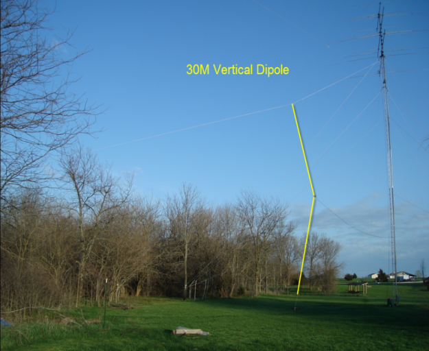
For 30m, a resonant vertical dipole is suspended from a rope running from the top of the tower off to the NE. The bottom end of the vertical is about 5' from ground, and the beam has a slight "V" shape as the feed coax pulls the center toward the tower The vertical dipole is resonant on the band and is fed with 75 ohm RG11 CATV coax with a run all the way back to the shack. The mis-match is slight and the antenna has been trimmed for best SWR which is under 1.5:1 at the rig. Spaced about 30' from the tower, the elevation pattern is pretty clean although the center tilt and the tower do cause the pattern to dip a bit on the SE direction. While there is no forward gain for the antenna, it is quiet as omnidirectional verticals go. 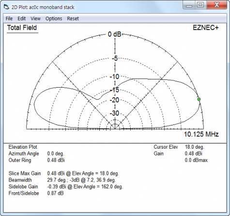
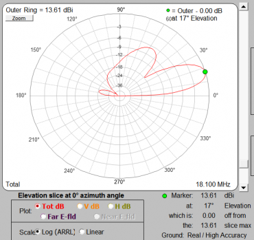
On 30m receive, the beverage and circle-8 array are alternatives. 17m - 3 element YagiThe 17m beam is mounted on a tilt-over tower (more tower details below) at about 33' high. The tower base sits on a hill that rolls off about 10' in vertical height over about 50' of horizontal run - and this slope adds importantly to the effective height on the North-beaming direction. The homebrew beam design was optimized with AutoEZ. AutoEZ brings automation functions to EZNEC including gain and F/B optimization. The homebrew antenna's taper was measured with the antenna built to rough dimensions. And then AutoEZ was used to fine-tune the beam's element length and position. Given the beam's 20' overall fixed length, a 3-element beam provided full use of the boom . AutoEZ suggested that adding a 4th element would not provide any significant performance benefit. Considering the desire to keep this tower as an unguyed structure, minimizing wind load on the tower was a higher importance than any incremental benefit an additional element (or a boom extension + 4th element combination) offered. The hairpin match was fitted to the SO239 center insulator connection and measured with the N2PK VNA in advance. As such, the beam was very easy to trim with only small increments of DE length required to adjust. 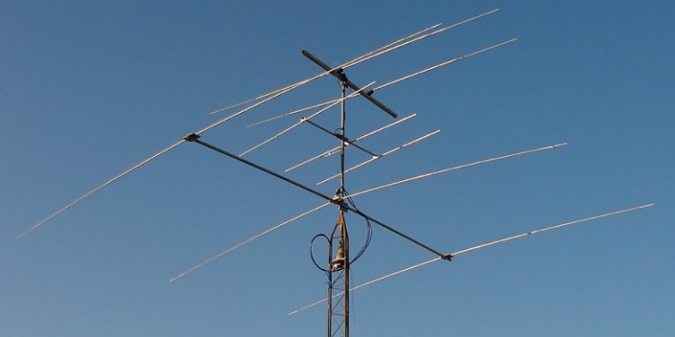
Looking first at the EZNEC modeled (left) and AutoEZ (right) elevation plots (assuming a net 43' as an average effective height for 270-90 degree bearings). Here the data are exactly in agreement as EZNEC is the source for the AutoEZ plots. 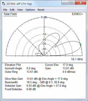
Comparing the modeled SWR (left plot, from AutoEZ) with the actual finished beam 's measured SWR
(right plot, from MyVNA + N2PK): 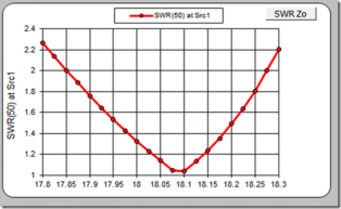 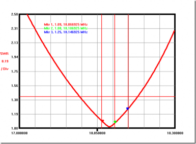
\ And this comparison of the modeled AutoEZ R/X plot vs. the actual finished beam's measured R/X plot from the VNA: 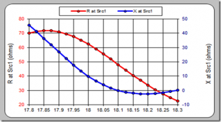
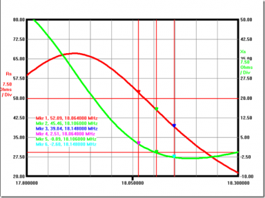
In both cases, there is excellent agreement between the model and the actual beam although we can see from the VNA measurements that the beam's DE trim is about 10 Khz above the model's target. The obligatory subjective observation: this beam works great! Especially compared to driving my 15m monobander in reverse. Epilogue: In preparing the graphics for the web page, I noticed that the beam design could be improved further. Originally, the design was optimized with "free-space" as the ground choice. Rerunning the AutoEZ optimization sequence over real-ground suggests I could improve the forward gain by 0.3 dB and improve the back-side rejection of the 2nd lobe by 5 dB or so. The trade-off is a longer 1st rear lobe extending out further another few dB. Seeing this result, I'm thinking that a disclaimer should be put on the simulation activity in general - something like "abandon all hope ye who start playing with this modeling program..." would be quite appropriate! EZNEC power users should take a good look at AutoEZ. For more information, see AC6LA Dan Mcguire's AutoEZ home page HERE. 12m - 2 element YagiFor 12m, a 2-element design was worked up and has been built out of KT34 parts. It sets at about 40' on the same tower as the 17m. Models indicate there is some interaction between the 17m director and the 12m which causes some fill in the back-side of the pattern. 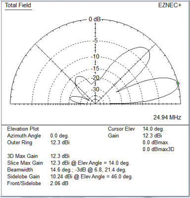
Sitting in the middle of these two antennas is a small 3-element commercial Cushcraft 6m antenna. About the Tilt TowerThe tower is built on a home-brew tilt base and anchored to the basket-ball goal. The specs for the basketball goal call for 16" diameter x 4' deep hole for the anchor bolts. While it's not known if the original builder followed these specs, it seemed a good place to anchor the WARC tower. The tilt base allows the tower to be lowered. A pulley at the top of the basket ball goal cuts down on the compressive force the tower base feels at the extreme angels. 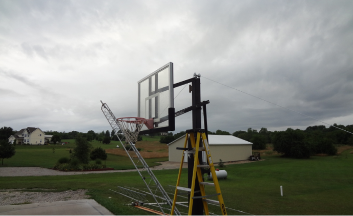
The tilt base is shown here. The 3 legs have sleeves providing a bit of extra support. 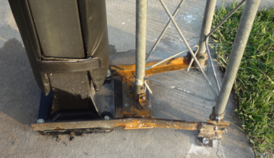
When upright, there is a half-circle support for the tower at about the 12' level. A U-bolt clamps the support to the tower. 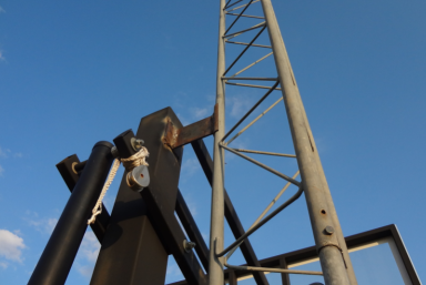
A short video of the tower being lowered is available for download (file size 6 Mb): AC0C WARC TOWER ==============================================================================Some analysis of WARC band use of the other antennas - while they are not being used for this purpose, the analysis is interesting... The 250 foot coax run out to the tower location means any of the shacks antennas can be loaded on the WARC bands with the cable loss covering a multitude of SWR and matching sins. And the Ameritron RCS-12 controller will allow on-the-fly overrides of presets for easy selection. An attempt at loss calculation was done with TLW and it's surprising how bad the losses are. The antennas work with reasonable directivity, but for transmitting, they proved very poor. 17m - Using the 10m Yagi in reverse or the 80m dipoleFor this band, the 10m Yagi works well as does the 80m dipole, depending on the signal source location. Here's the 10m yagi plot: 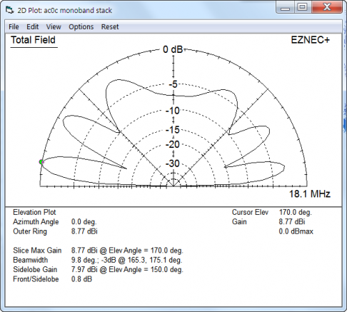
And this is the 80m dipole plot, in the NE/SW orientation. The antenna has varying responses in other directions but this is the best and fortunately aligns well with EU. 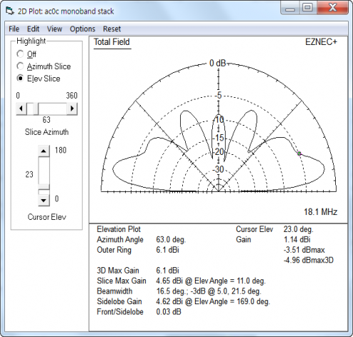
The dipole is the better runner of the two as the losses are less. Model estimates about 2 dB for the SWR and 5 dB for line losses for the dipole (fed by RG-213). The feed point of the beam is about 30-j125 and the losses are worse here, about 5 dB for SWR and 8 dB (RG-213) for the line totaling13 dB! 12m - Using the 10m Yagi in reverseFor this band, the 10m antenna has a good pattern. The hump along the top is due to the proximity to the 15/20m beams and the closeness of this band to the 15m beam. 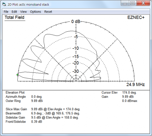
Model estimates about 3 dB for the SWR and 5 dB for line losses for a total of 8 dB. |