For the critical band pass filtering role, the 5B4AGN filter project looked like a winner! 5B4AGN home page: http://www.5b4agn.net/ Yahoo Support Group: http://uk.groups.yahoo.com/group/TXBPF/ Based on the benchmark setting W3NQN filter design, this project should offer performance of the top end commercial offerings and at quite a significant savings. It's perfect for guys who like to fiddle with filters! I was very fortunate to catch Bob just a few days before closing of the last group buy. Great timing. Stock photos and feature list pulled from the 5B4AGN web site and shown below. 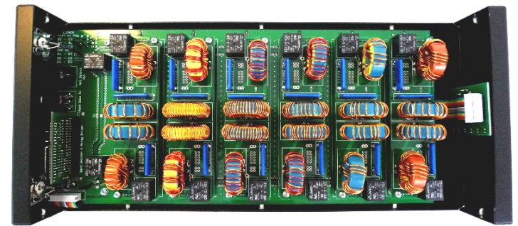
- Self contained unit for the 6 HF contest bands.
- Band filters and associated select relays assembled on individual daughter boards providing for replacement on failure without withdrawing the complete unit from service.
- 100W or 200W rating dependent upon user preference.
- Interface directly with transceivers providing 250mA current sinking band line drivers. E.g Ten Tec Orion
- Optional plug-in band data decoder and antenna relay driver configurable for current sourcing or sinking antenna relay drivers. Band data decode in Yaesu format, providing direct compatibility with Yaesu binary band data outputs and with the Elecraft K3.
- Configurable for "no filter selected" by-pass or open circuit.
- By-pass low SWR to VHF.
- Front panel rotary band switch for local/remote filter selection with LED indication of band in use.
- Performance compatible with stand-alone W3NQN filters. i.e. Not materially compromised through use of motherboard.
- DB9 connector pin compatible with Dunestar 600 providing for direct substitution where required.
- Configurable for Dunestar compatible +ve or -ve keying .
- 5 Pin DIN connector for control using binary band data.
- 8 Pin DIN connector providing access to antenna select relay drivers.
- RF path via 2 standard SO239 connectors.
The Parts 5B4AGN sells the component kit in 3 increments - the PCB set, the hardware and the PCB parts. Everything except the case, toroids and toroid wire is contained in these initial kits. The wire was purchased from Bulk Wire. 1 lb each of 18 and 16 GA. The toroids were purchased from Diz in a kit that is listed under the W3NQN filter name on his site. The cases (not shown) are arranged via an EU vendor under 5B4AGN's coordination and will arrive later. 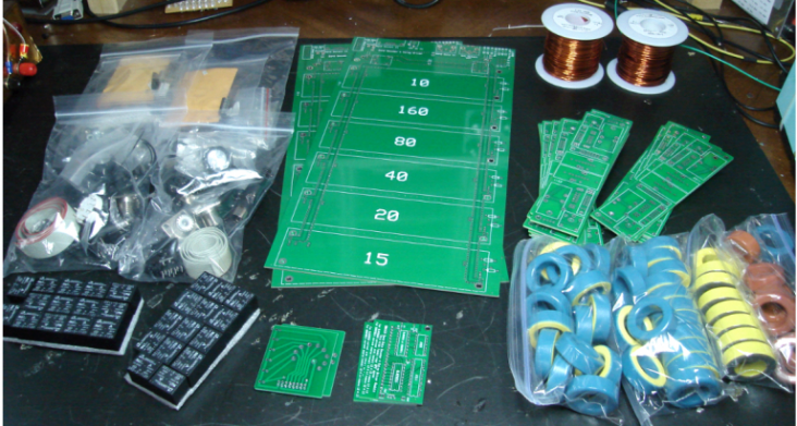
The Build The mother board and the individual filter boards are prepared first. 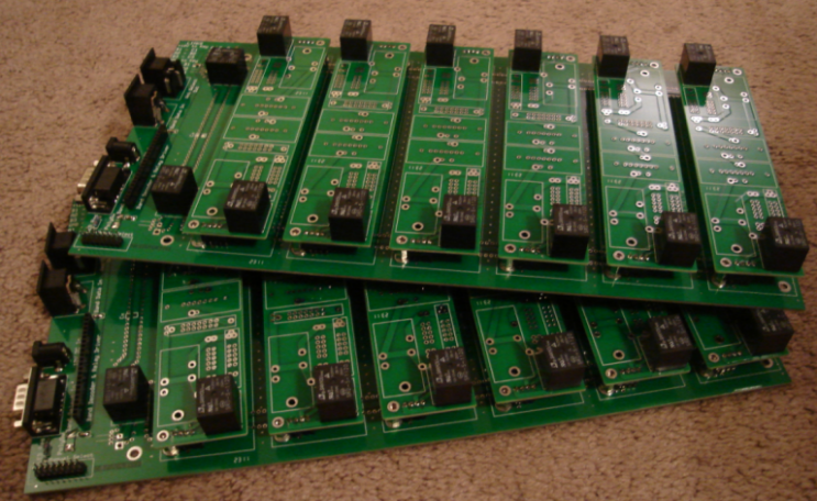
With the motherboard completed, I built up a set of the 10m filters because the number of turns on the coils is the lowest.and I thought that would be the easiest band to learn the coil wrapping method indicated by 5B4AGN. 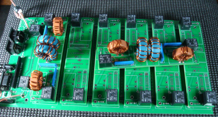
The design is a 3-pole Chebyshev design originally made popular by W3NQN. The thin blue elements are capacitors custom made for the project by Tab in the UK - tight tolerance and high RF current capacity capable. 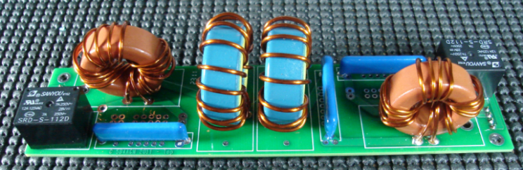
The wide sweeps from the two completed and adjusted filters shown here. The large "bump" in the graph near 4 MHz is not as pronounced with the boards properly grounded and secured in their normal position. To allow for playing around, I purchased a few extra filter board modules. And want to initially add a notch to the 15/20 pair as that is the worst-case coupling combination on the antenna side. Filter fun awaits!!! 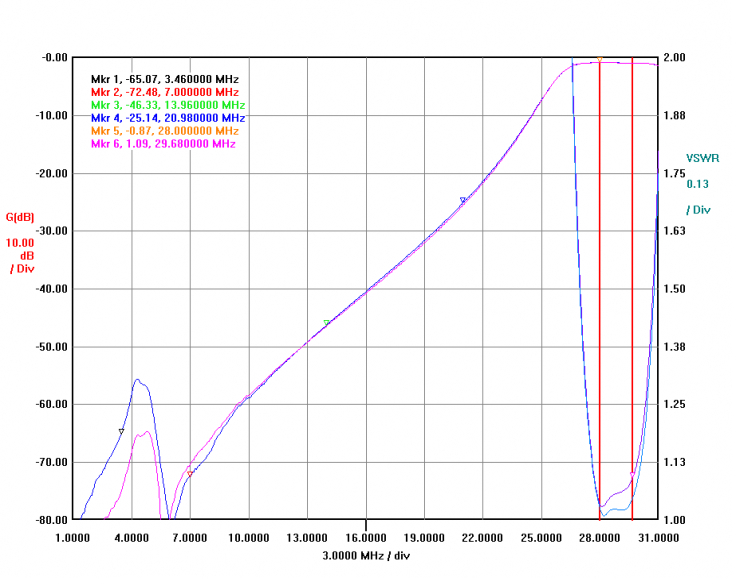
A narrow frequency sweep of the pair here. 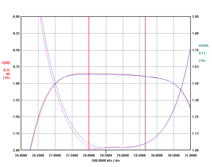
The Finished Board The boards are finished now and look like this. Only remaining work is to mount the boards into the case once they arrive. The BCD decode data (shown on the top/right of the picture below) will accept band data inputs from the Yaesu and switch the BPF boxes to the proper band accordingly. On the WARC and 6m bands, the filter is bypassed. The rotary switch tied to the board by the ribbon cable allows manual operation of the band data decode if it's not connected. 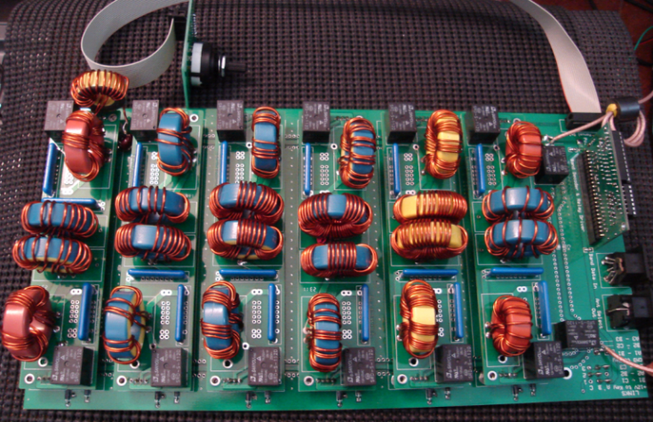
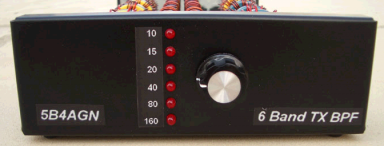
Completed Build Photos Front view, with labels attached. Labels were generated with a Brother P-Touch using white-on-clear label stock. 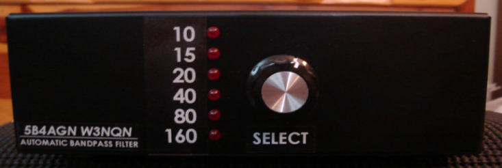
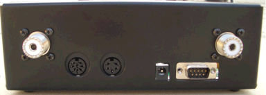
Rear panel view. 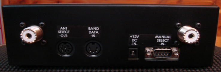
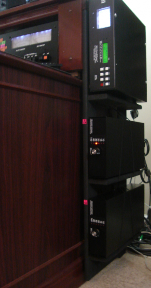
The two filters are mounted in the shack on the right side of the desk table which has become the "command center" - shown at left. Above the two band pass filters are visible the MFJ-998 auto-tuner and the Alpha 76pa. Initial Finished Board Attenuation Plots Two lines on each graph represent the two filter sets. These generally line up closely - variations are due to differences in tune and coil winding primarly. VNA plot measured data shows: Marker 1 - Minimum loss frequency Marker 2 - Low side, 1db down frequency (except on 15m, where it's 2 db down) Marker 3 - High side, 1db down frequency (except on 15m, where it's 2db down) Marker 4 - Ajacent band attenuation Marker 5 - Ajacent band attenuation Marker 6 - Ajacent band attenuation Marker 3 - Marker 2 : calculation of the -1db bandwidth of the filter passband 10m BPF 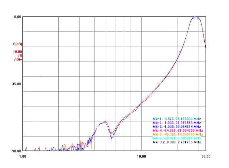
15m BPF - with preliminary trap for 20m added 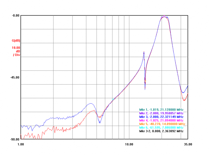
20m BPF 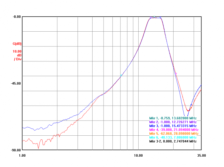
40m BPF 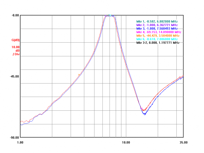
80m BPF 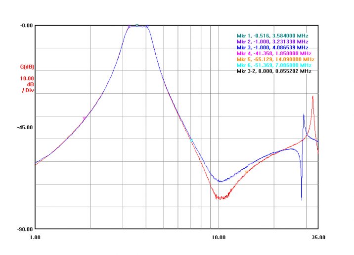
160m BPF 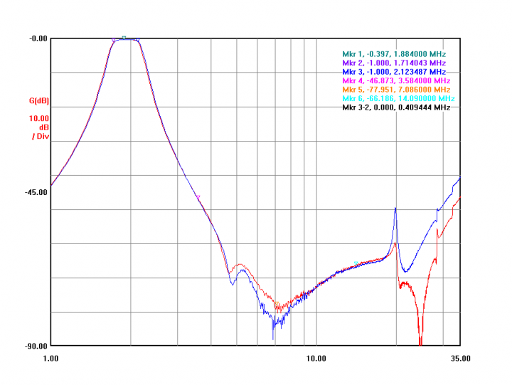
|