Taking Help Wherever We Can Find It Toward our goal of 135 db total attenuation, the rig preslectors will offer some assistance. The block diagram of the preselector for the FT-2000 is this, showing the VRF and the preselector (BPF UNIT). The VRF analysis will be shown on another page HERE 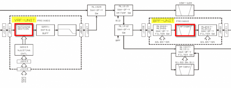
For the FT-5000, the preselector block diagram looks similar: 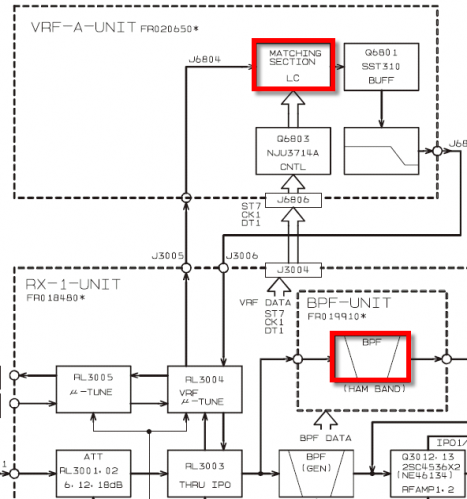
To get an idea of the attenuation the BPF preselector will offer in our SO2R configuration, the fast method is to use the excellent Elsie filter simulation program. FT-2000 Preselector Cross-Band Attenuation Simulations The implementation in the 2K is a 7-pole LPF section and 7-pole HPF section in cascade. A typical section looks like this: 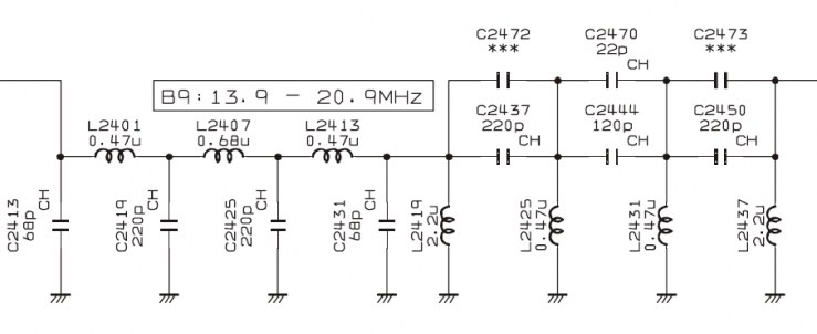
The FT-2000 has a total of 6 preselector bands, with operation frequency ranges listed in the schematic. Each segment is automatically selected by relays driven by the rig's controller chip. The operation is fully automatic and as such is transparent to the operator. The preselector selection serves both the main and sub receivers (which is why the sub receiver cannot receive well signals for bands outside the main receiver's current preselector range). Band | Marked Range | 1 | 1.7-2.5 MHz | 2 | 3.4-4.7 MHz | 3 | 4.7-6.9 MHz | 4 | 6.9-9.9 MHz | 5 | 9.9-13.9 MHz | 6 | 13.9-20.9 MHz |
Because of the Elsie program limits, only 7 poles could be simulated each time. So I looked at the effects of the LPF and HPF section for each filter of interest separately. With planned operation of the FT-2000 restricted to 20 and 40M, a total of 4 schematics were built and simulated. An example of the resulting transmission plot is shown here: 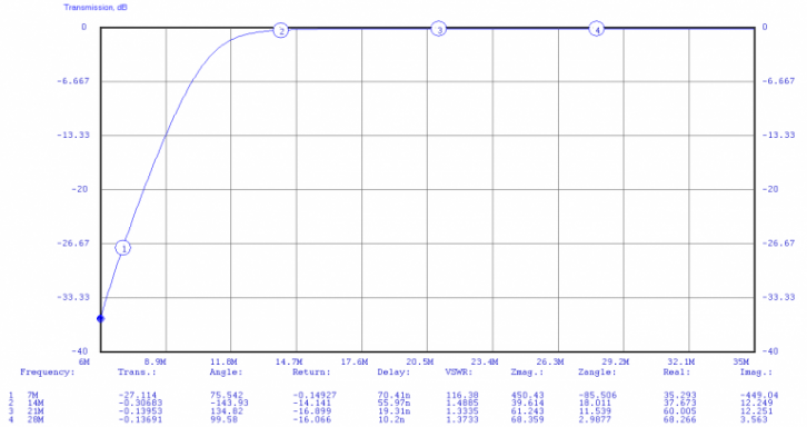
In this example we are considering the case of another transmitter on 40M, and the FT-2000 operating on 20M. Here, the band 6 preselector (13.9-20.9) would be in-line. And we should expect around 27 db of attenuation to a 40M signal present on the antenna inputs, when the rig is tuned to 20M. Attenuation levels for the other band combinations of interest are: Other TX | Rig Tuned | Presel Band | Attenuation | 15M | 20M | 6 | 0 db | 40M | 20M | 6 | 27 db | 20M | 40M | 4 | 3 db | 80M | 40M | 4 | 16 db |
The analysis says that the preselectors' are going to be of some help when the FT-2000 is operating on the next band higher, but the preselectors' are going to offer little help in the case the FT-2000 is operating on the next lower band. Specifically in the case of 15M interference with the rig tuned to 20M, the LPF is of no help. That's because the filter roll-off as well as the corner frequency are quite high. 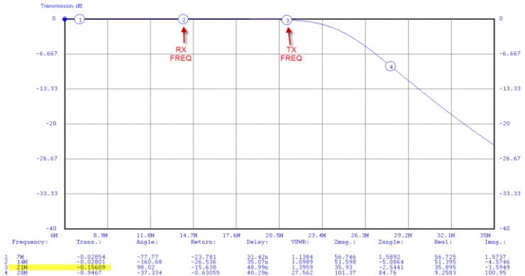
While the BPF module is easy to remove from the FT-2000, it's likely much simpler to incorporate 15m notch elements either directly into the automatic 5B4ABN BPF unit as well as possibly placing a 15m coax notch or other L/C combination element directly on the 20m antenna line. So we come away from the analysis with a mixed result. Some helpful combinations - and some unhelpful. The good result here is that we now know which combinations will likely need the focus - the higher side band attenuation. FT-5000 Preselector Cross-Band Attenuation Simulations The FT-5000 has a similar preselector structure although a different circuit implementation compared to the FT-2000. The main receiver has a dedicated sub-board with 8 band ranges. The sub receiver's preselectors are contained on the TRX board. The analysis below is specific to the main receiver preselector bank. An example of the 5K preselector design is this 20/17m filter here: 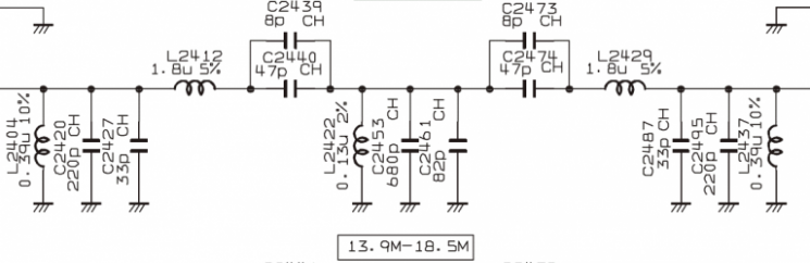
Main receiver preselector ranges, specified in the schematic are: Band | Marked Range | 1 | 1.7-2.1 MHz | 2 | 3.4-5.0 MHz | 3 | 6.9-7.5 MHz | 4 | 9.9-10.6 MHz | 5 | 13.9-18.5 MHz | 6 | 18.5-24.5 MHz | 7 | 24.5-32 MHz | 8 | 47-56 MHz |
Combinations of interest for the FT-5000 are different than the FT-2000. Based on the simulation, the estimated attenuation expected from the FT-5000's preselector are much better than what we see from the FT-2000. Other TX | Rig Tuned | Presel Band | Attenuation | 20M | 15M | 6 | 21 db | 20M | 40M | 3 | 66 db | 40M | 20M | 5 | 59 db | 40M | 80M | 2 | 27 db |
The simulation plots for each of the 4 bands are shown below. Rig op frequency: 15m 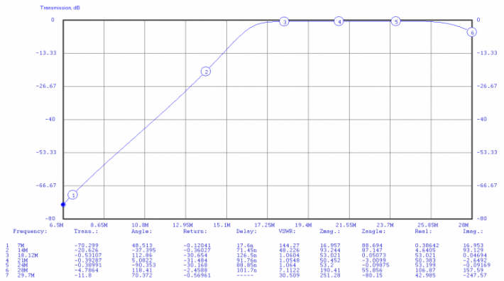
Rig Op Frequency: 20m 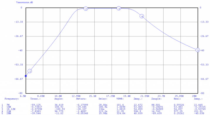
Rig Op Frequency: 40m 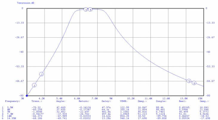
Rig Op Frequency: 80m 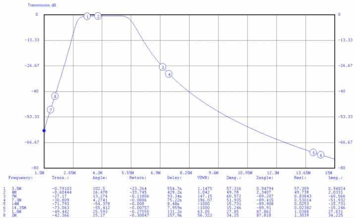
The changes Yaesu has made to the FT-5000 preselector looks very good. With nearly 60 db of average attenuation on the 20/40m combinations, we have an excellent chance that the FT-5000 will remain unaffected by the FT-2000 output assuming we have a 0dbm signal into the rig on these two bands; great news given these are the core "working" bands. And we even get a bit of help on the troublesome 15/20m combination. |